PokéBoy
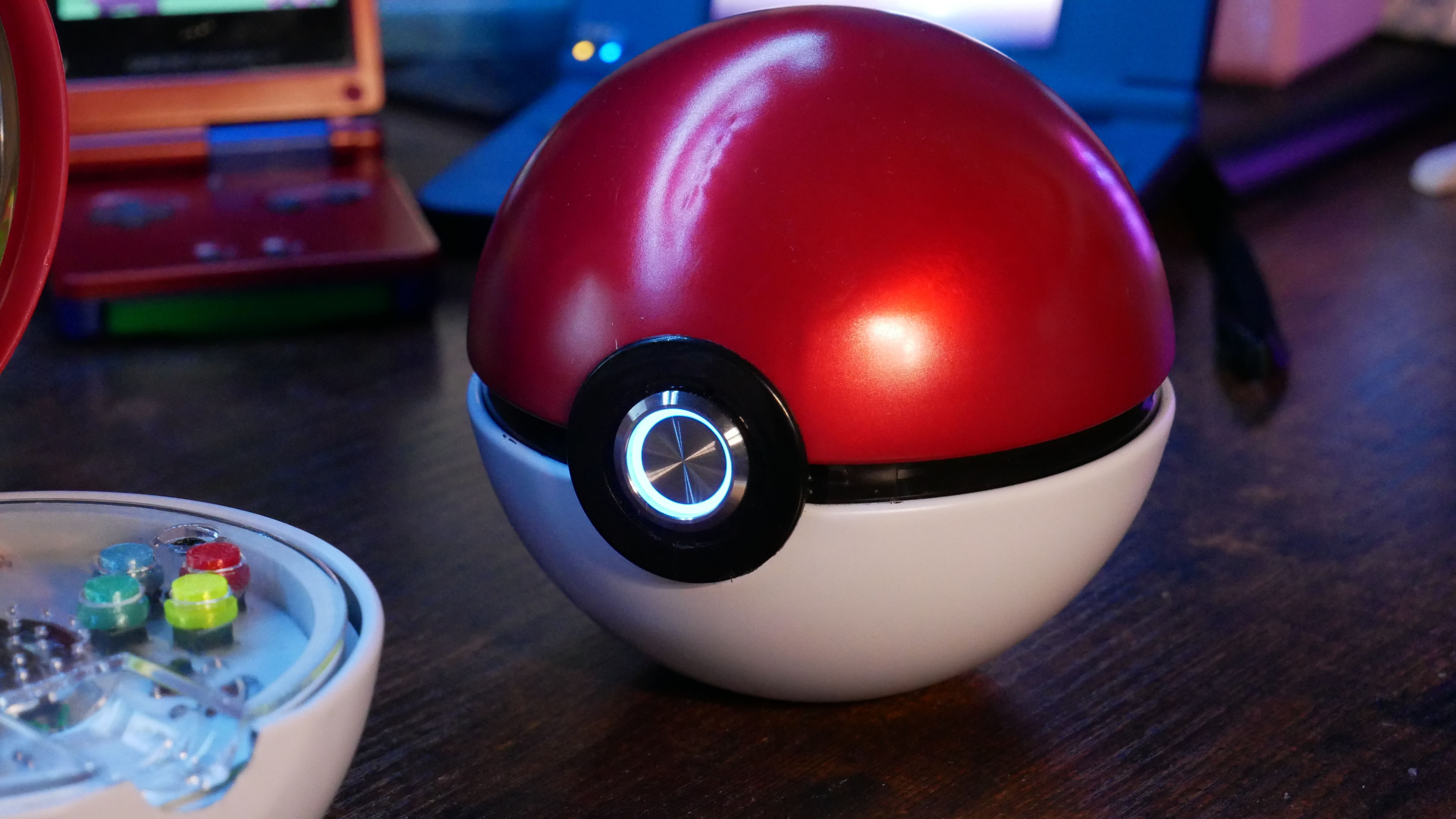
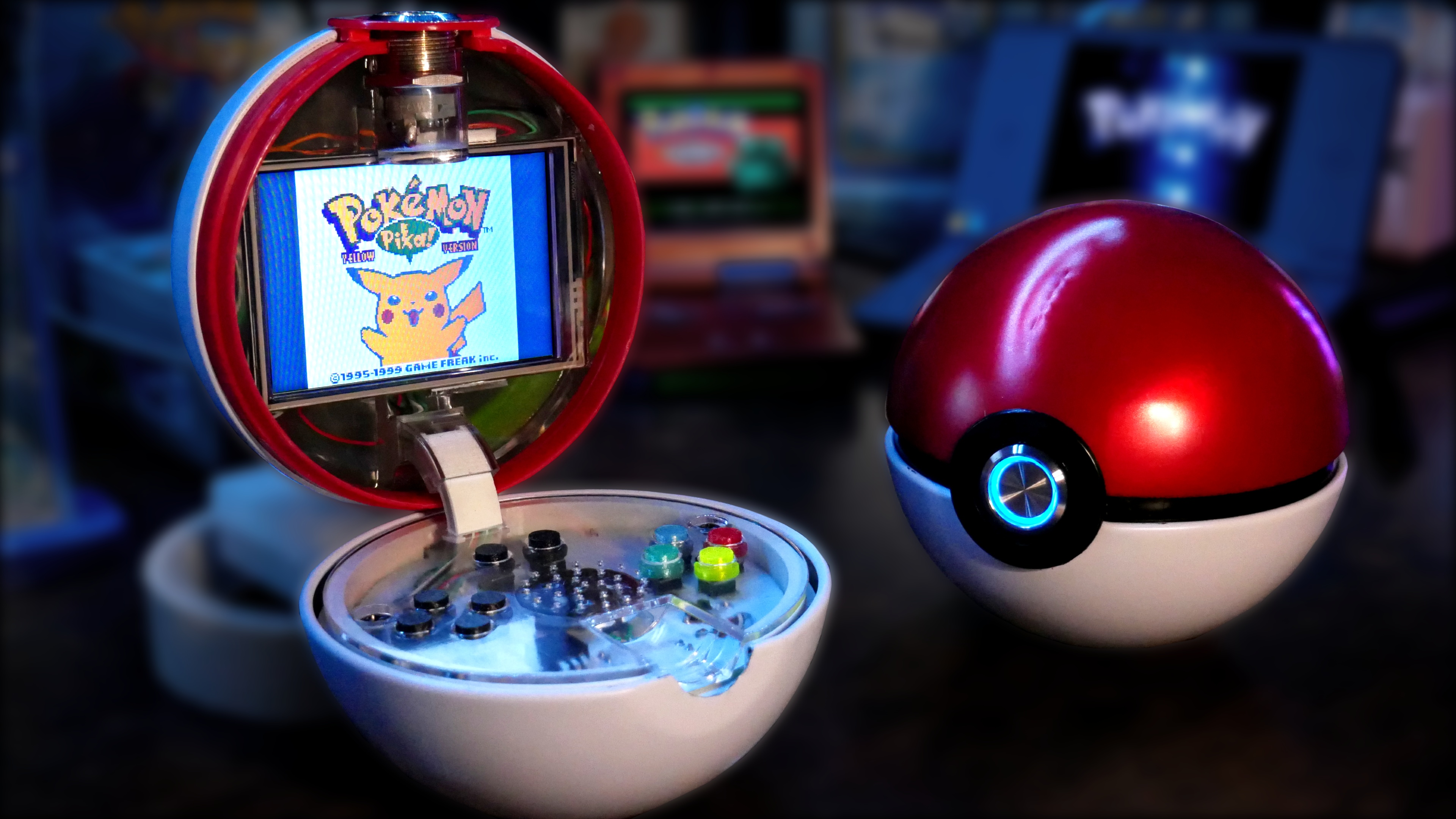
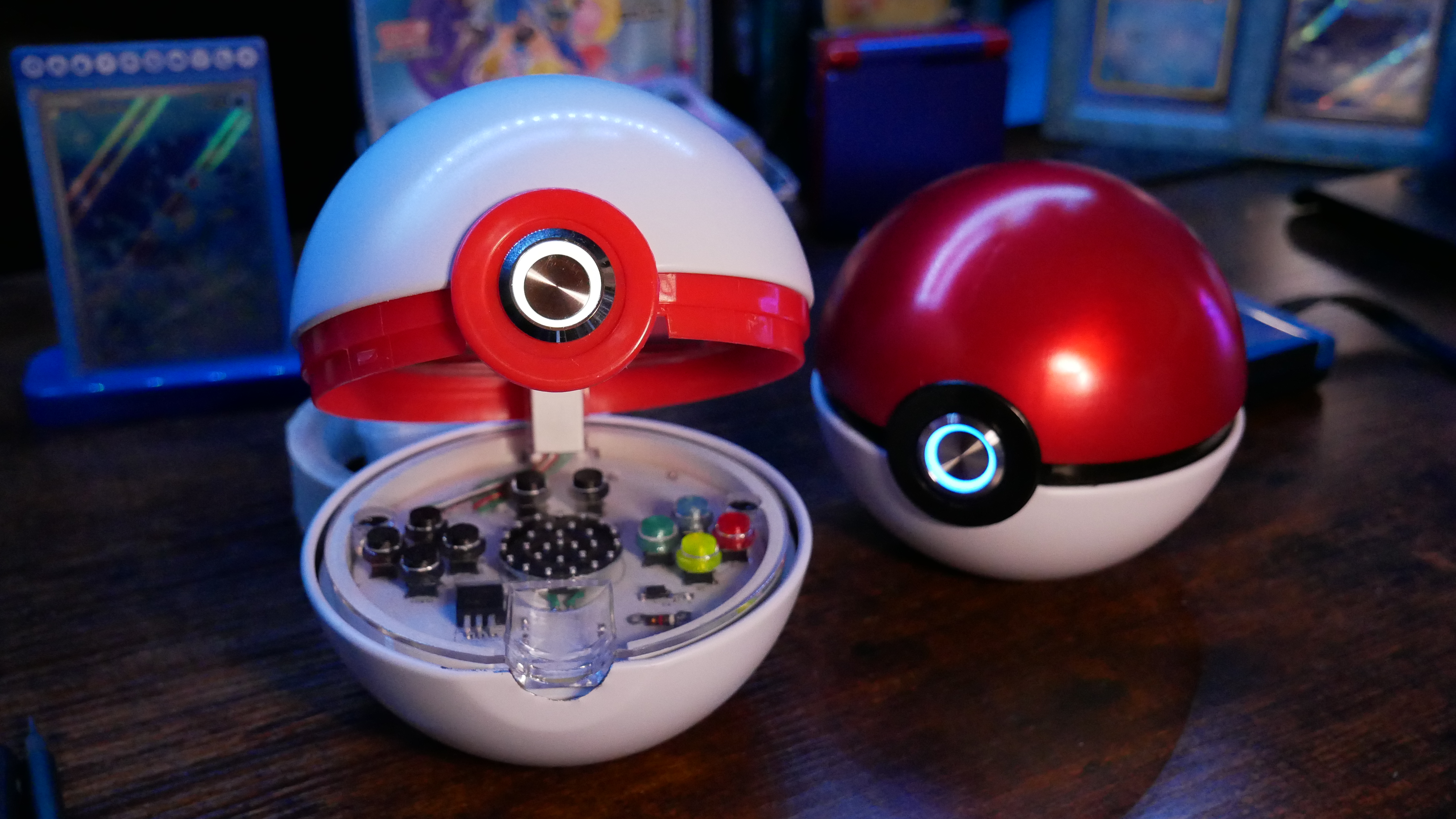
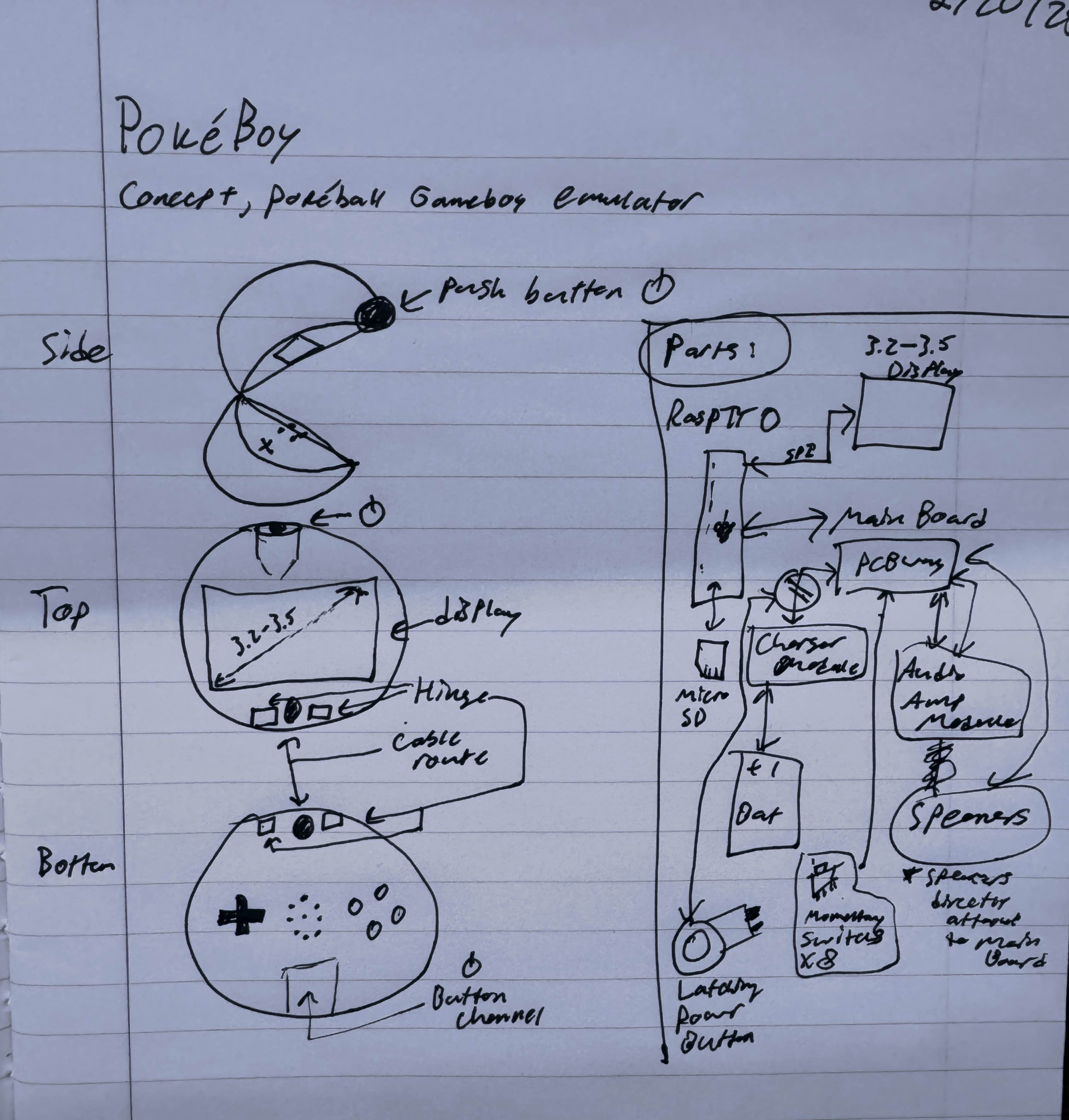
> Welcome to the PokéBoy project! With the help of PCBWAY as the project sponsor, I developed a retropie project that would fit inside a standard store bought TCG Pokéball, because what else are you going to do with it?.
> This page will serve as a build guide if you ever wanted to make one, *I am not responsible for whatever outcome that might occur; like if you anger Arceus, that's not on me*
> Before we start, I highly recommend watching the full video on the PokéBoy below for a general overview of the build. Also keep in mind that this isn't really the ideal console to play on, there are no LED indicator to tell you when it's low, and play time is low (2-3hrs) off the battery so it might need to stay plugged in. If you did the display (advanced) step, the screen will start glitching out at low power so that in itself is a power indicator lol. It is still a cool and fun build though, so have fun if you just like the novelty!
Parts
> Below are 3 links, the first one allows you to download an excel spreadsheet containing a BOM of every necessary component other than tools and wires. (you might have to port it to google sheets)
> The other two links will lead you to the PCB and CAD files respectively, I highly recommend ordering/sourcing/printing everything here while you mentally prepare.
> Tools you will need: soldering iron, solder, epoxy, hot-glue, files, and thin stranded-wires (about 0.7mm in diameter with insulation). A breadboard and multimeter are also helpful.
Setting Up The Pi
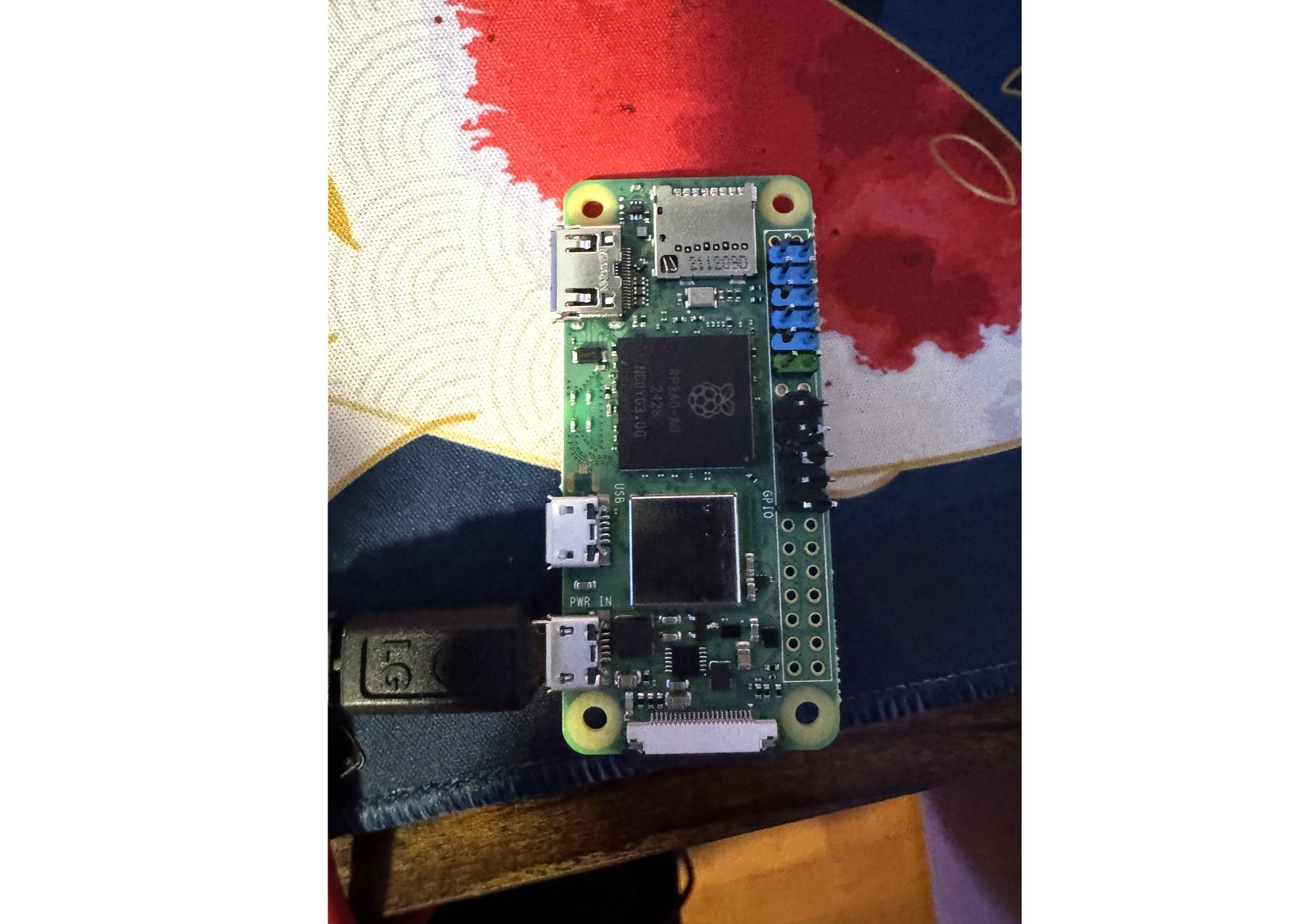
> We can't solder all of the headers onto the Pi because we need to leave room for the other wires later, leave the first row clear, solder on the next 6 rows, leave the next one clear, then solder on the next 5 rows and leave the rest clear.
> One of my biggest concerns with this project is, "how long will it last before things get outdated?" There will likely be newer Pi's and firmware, so I suggest testing them first before we assemble anything. As of right now, I used a raspberry pi zero 2W and retropie-buster 4.8. (You might be able to use an orangepie and other fruits, but their installations for retropie might require an O.S. thus will have varying steps from this guide).
> As of right now, you need to install retropie using an externally downloaded image to apply a custom profile (necessary for enabling SSH on install) You can download retropie and the Raspberry Pi imager from the link below:
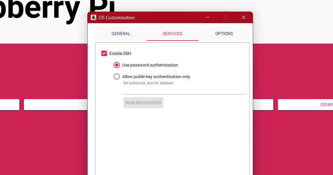
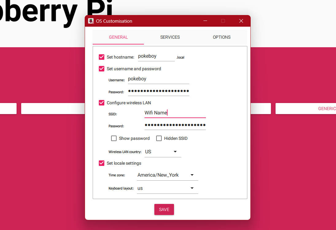
> Open the imager and enter the advance menu by pressing CTRL+SHFT+X. In the services tab, enable SSH, then in the general tab, set the hostname and username to pokeboy, set your own password. Uncer "Configure wireless LAN", enter your wifi name in SSID, then the password. Hit save (CTRL+X).
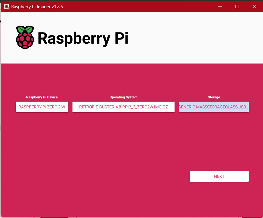
> In the imager, select the Raspberry Pi Zero 2W as the device. For operating system, select "Use custom" at the bottom and select the image that you downloaded. Select your SD card as storage, hit "Next", then "Yes" to apply custom OS settings.
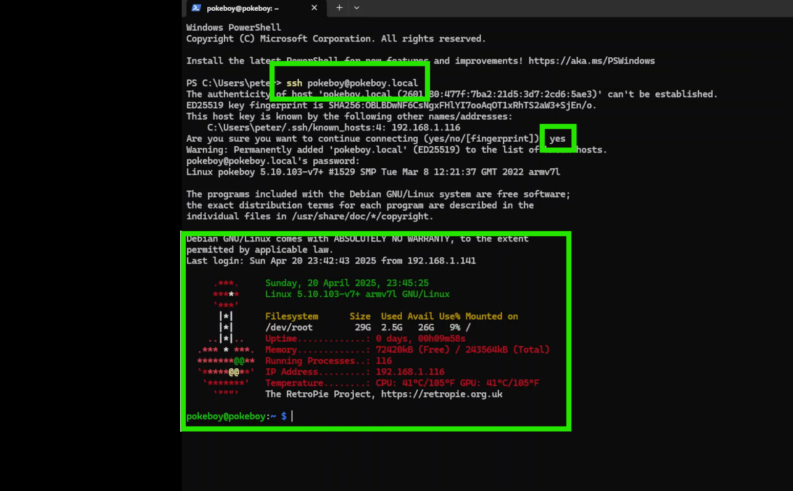
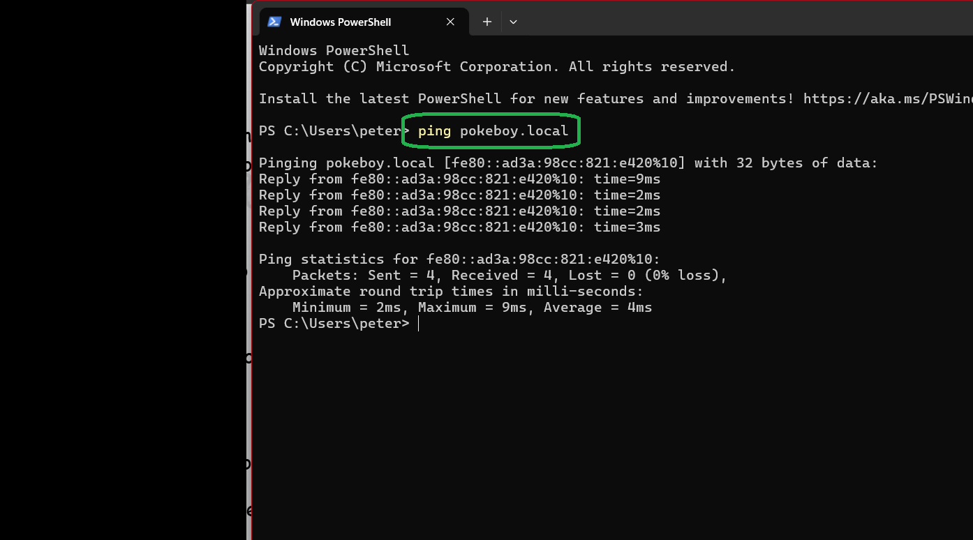
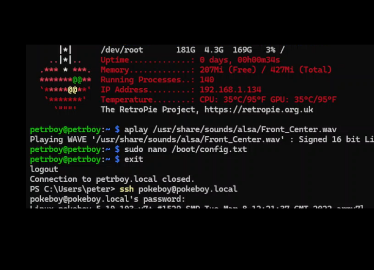
> Insert the SD card into the Pi and power it on, give it about 5mins to run any setup processes and find your network. Then open a terminal like windows powershell, run:
ping pokeboy.local
to make sure the Pi is on the same network as your PC, it should send some kind of reply back.
> To connect to the Pi, use:
ssh pokeboy@pokeboy.local
You will be prompted to set up the fingerprint, type "yes", then enter your password to the Pi
> Here is a helpful video to follow along. The steps are not exactly 1:1 but it should help!
> If you still have trouble, install retropie as normal and configure SSH later (you will need to plug in an external monitor and keyboard for this)
> Next, we'll install and update the firmware to the Pi. Run:
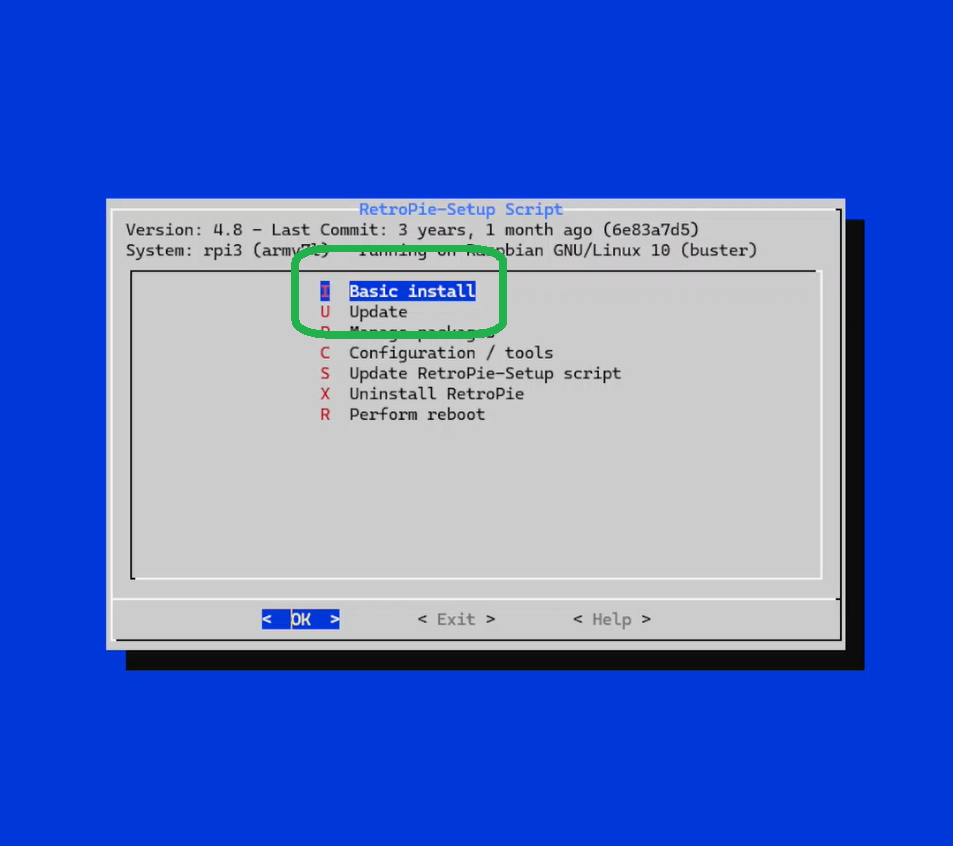
sudo ./RetroPie-Setup/retropie_setup.sh
then select the basic install, followed by the update afterwords
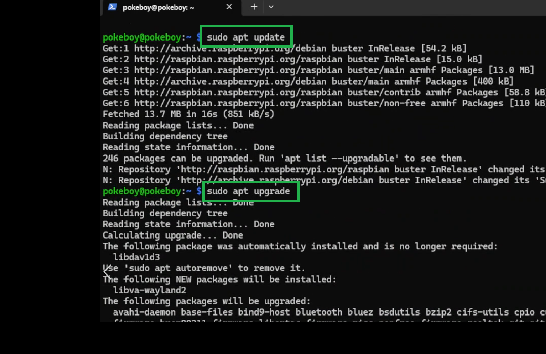
> Exit, then run the following two lines to finish updating everything under the sun and then some:
sudo apt update
sudo apt upgrade
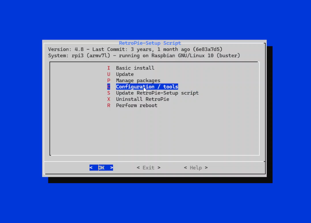
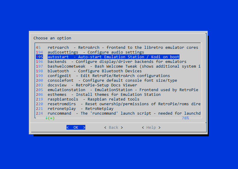
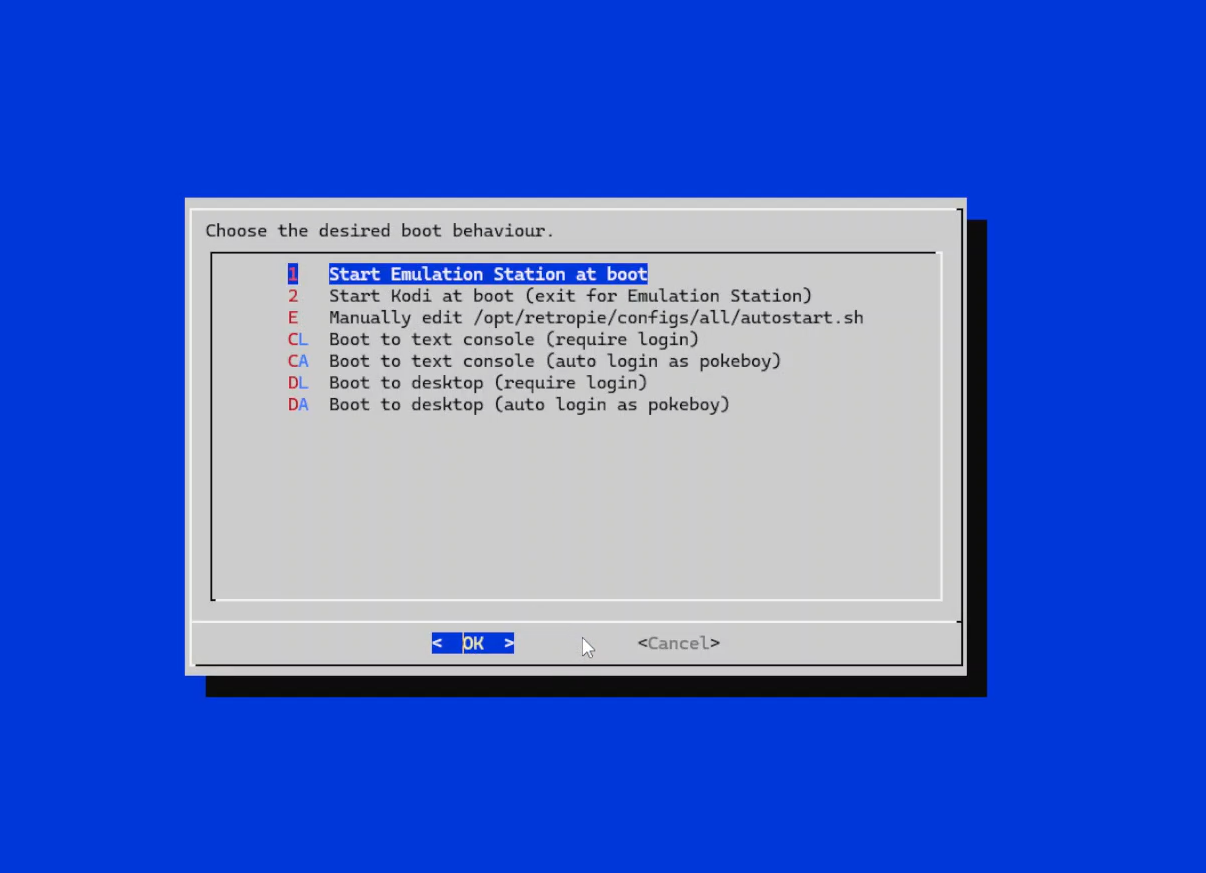
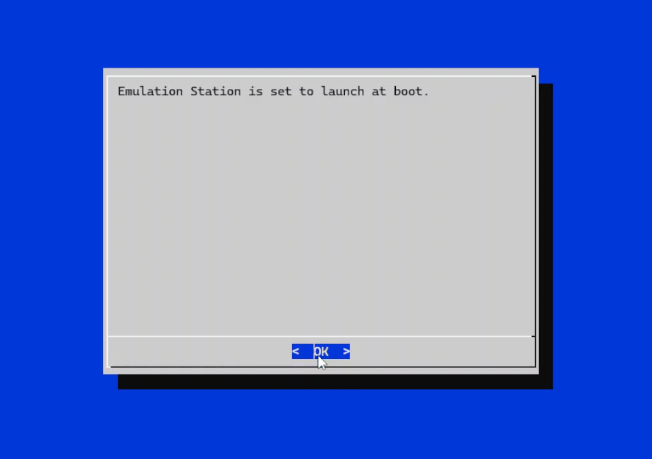
> We want the emulator to launch from boot, so re-enter the startup menu with ..retropie_setup.sh, select configuration, select autostart, and select the first option to startup emulation station at boot. After the confirmation page, you can select ok -> cancel -> exit.
Display
> *NOTE* the default drivers are actually terrible. It is definitely playable but at like 5 frames per second, which is bad. I recommend doing this step if you feel like the section "Display (ADVANCE)" is too difficult or if you simply just want to make sure that the display actually works first. Otherwise, skip to "Display (ADVANCE)"
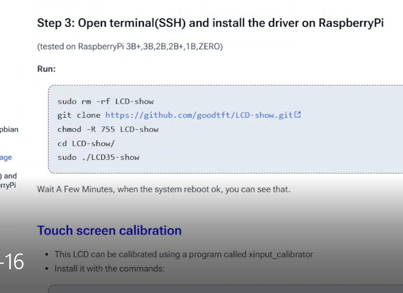
> We'll install the drivers for the display next. The LCD will likely come with a set of instructions, below are the commands required for the LCD I attached in the BOM *note, they have multiple variants of this screen, select the final command dependant on your variant*.
sudo rm -rf LCD-show
git clone https://github.com/goodtft/LCD-show.git
chmod -R 755 LCD-show
cd LCD-show/
sudo ./MHS35-show *OR* sudo ./LCD35-show *OR* other
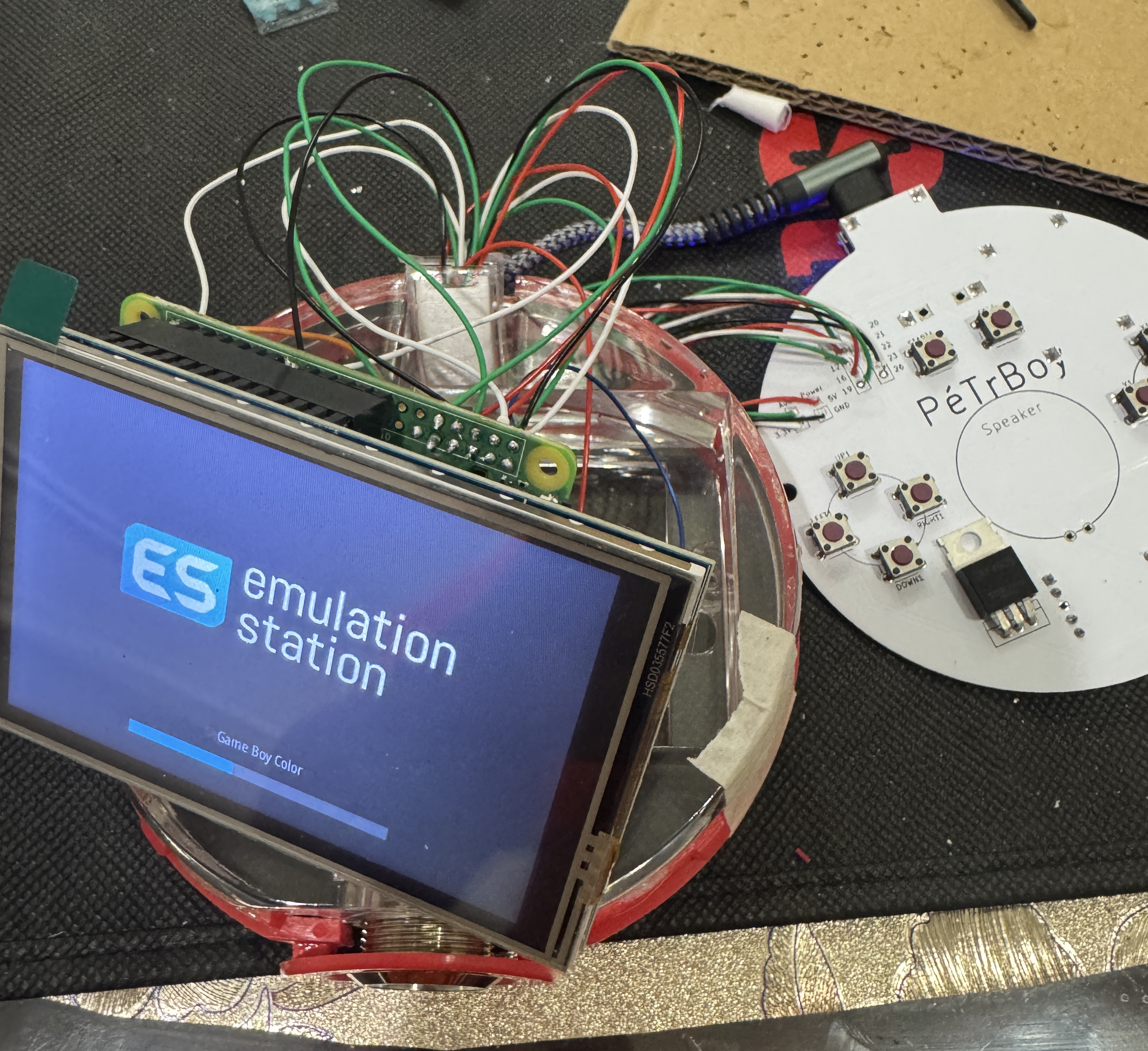
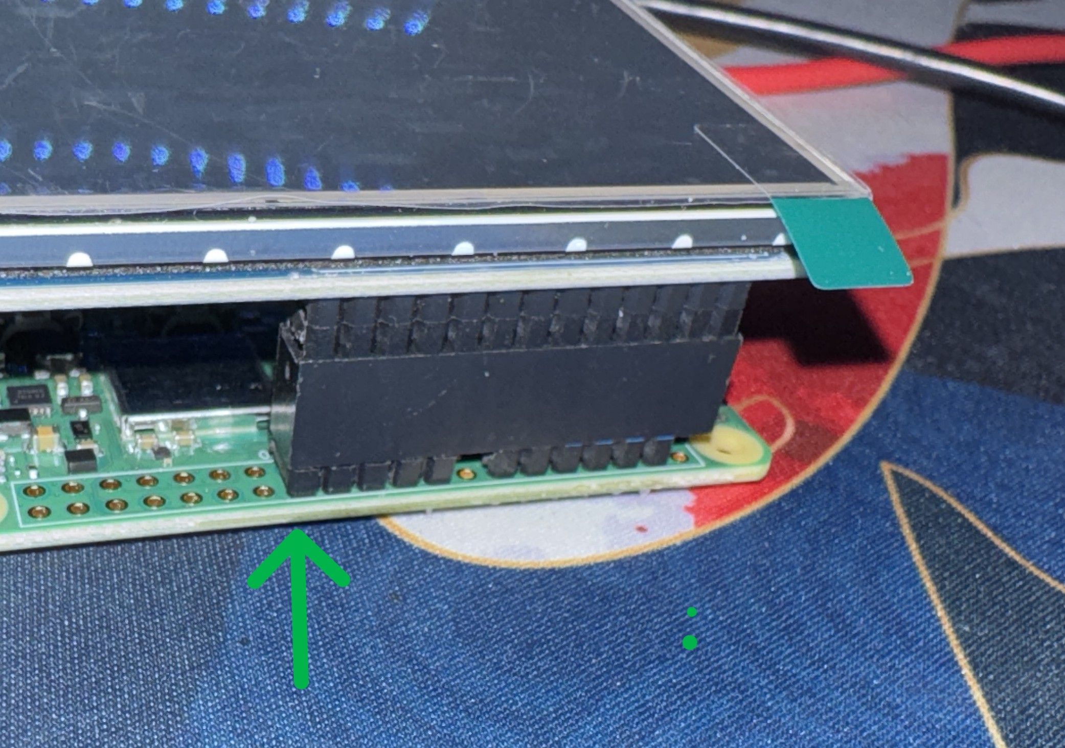
> Disconnect the Pi, plug the display onto the Pi aligning the bottom headers (remember the top row should be missing), then power the Pi back on and reconnect with SSH. The display should show emulation station after a brief white screen.
Display (ADVANCE)
> So the default drivers that comes with the display's instructions are actually terrible. The screen uses the SPI protocal which is a method to speak with the screen, and its kind of slow. That means we can't send a bunch of data to it too quickly, which is what the default drivers do.
> In this section, I will link a VERY helpful video by Bytes N Bits. They will walk us through the uninstallation of the default drivers (if you installed them) and to build/run some custom drivers. The key difference is that the new drivers will only update the pixels on the screen that changes color instead of the whole screen, which means we only need to send very little data at a time allowing for the screen to update faster.
> In the video below, there is a line of code that is specific to your screen, my screen uses the "ILI9486" chip (most of them will), so my cmake line looks like this:
cmake -DWAVESHARE35B_ILI9486=ON -DSPI_BUS_CLOCK_DIVISOR=20 -DSTATISTICS=0 ..
*note* play with divisor value, I found that below 20, the screen got glitchy, also keep the ball plugged in while doing this, I don't think the battery is enough to run make -j.
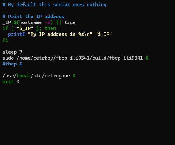
> Unfortunately, I do not think that the video covered how to make the driver autostart, to do that, we need to go back into the rc.local folder, and tell it to automatically run.
sudo nano /etc/rc.local
> *NOTE* In the photo below, my unit is named the petrboy, but you would use pokeboy or whatever you set the username to be
> Then, under where it says "sleep 7" add the following line:
sudo /home/pokeboy/fbcp-ili9341/build/fbcp-ili9341 &
> If you run into problems, check out the github below for more options/details on the custom driver, and do not hesitate to email me questions if you do get stuck!
> p.s. if there is a black border on your screen, you can increase screen resolution. Once in Emulation Station, select "RetroPie", then "RASPI-CONFIG", then select "display options", and select "default", then reboot. If that doesn't work, select a different resolution and change back, idk its weird like that.
Pinout Note
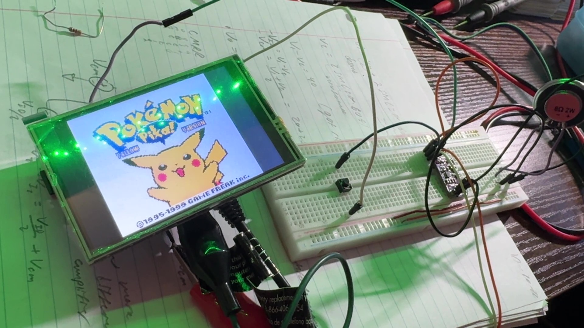
> The next steps, it might be helpful to have a breadboard, that way you can test the audio and button setups... or you can blindly trust these instructions because we're both just that good.
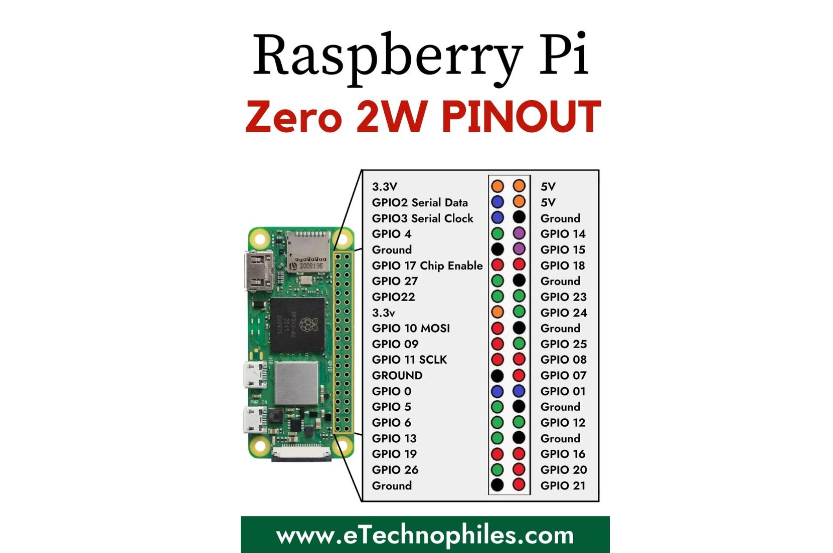
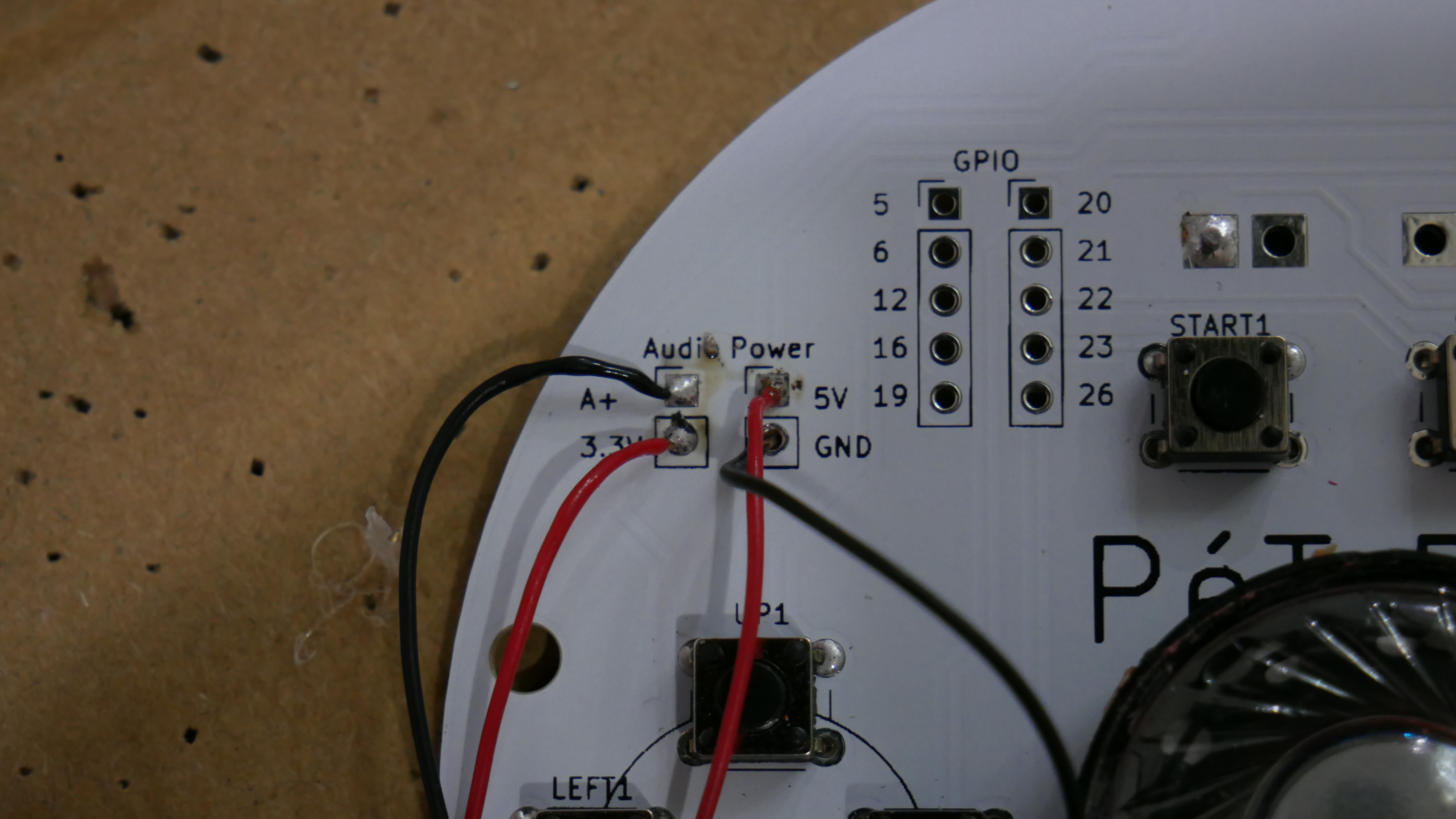
> Use the following photo to reference where the GPIO pins are (right click then "open image in new tab")
Audio
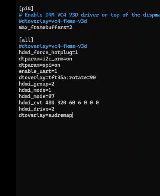
> To setup audio, we need to enter the config file by running:
sudo nano /boot/config.txt
then scroll to the bottom to add the following line:
dtoverlay=audremap
this will automatically set the audio pin to GPIO 13. You can then save and exit (CTRL+X).
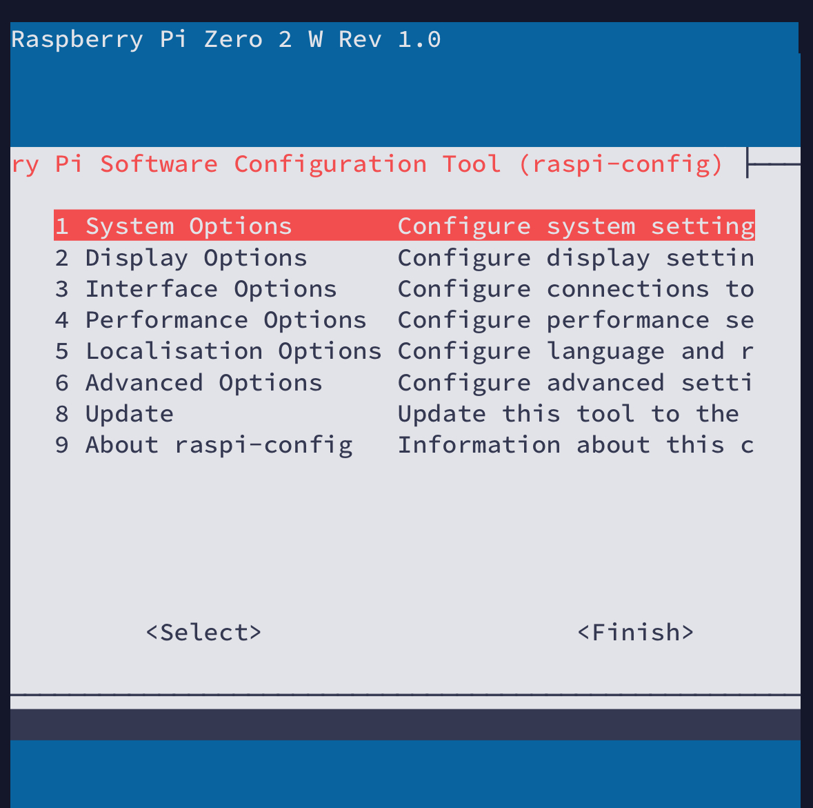
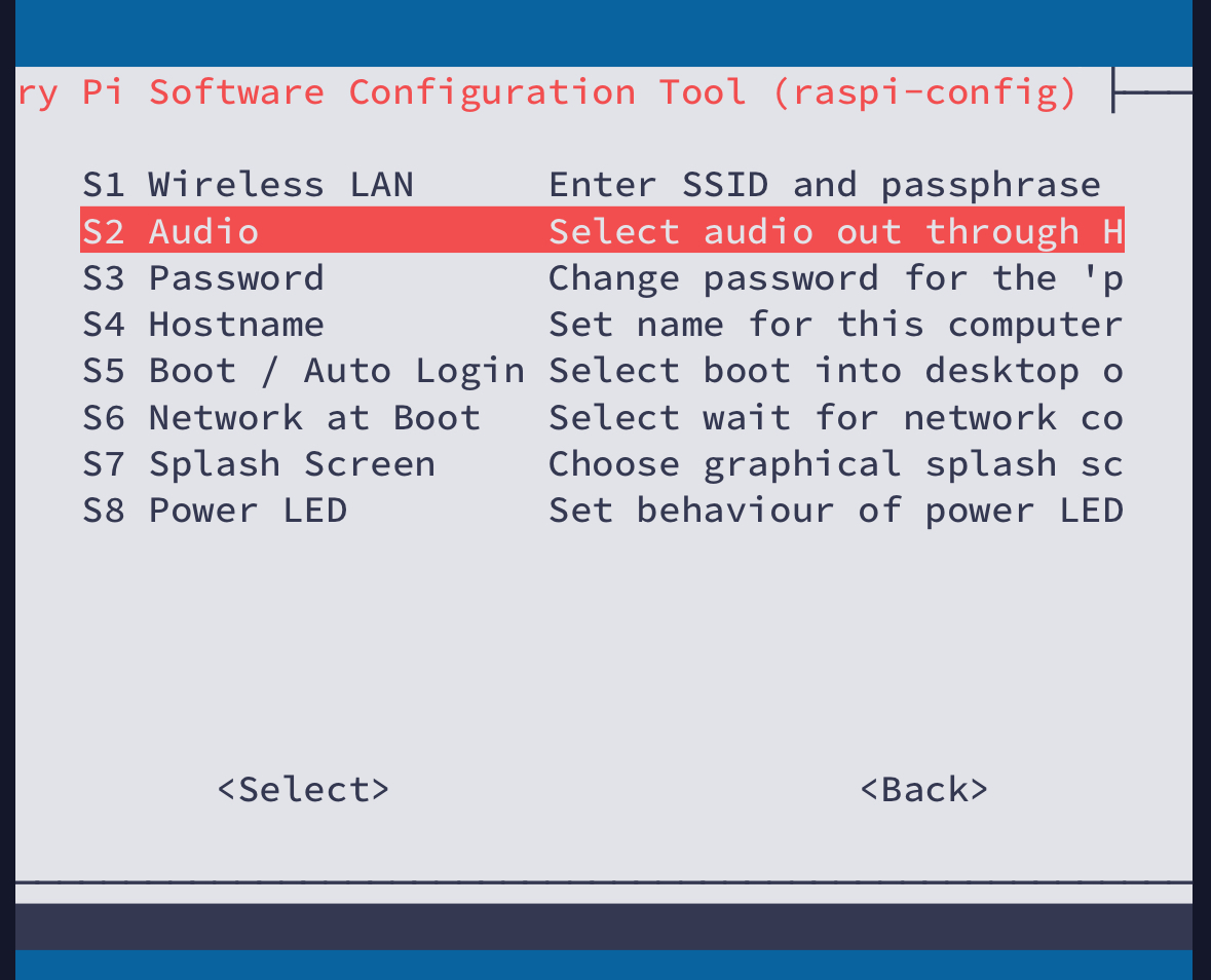
> Reboot, then, run the following:
sudo raspi-config
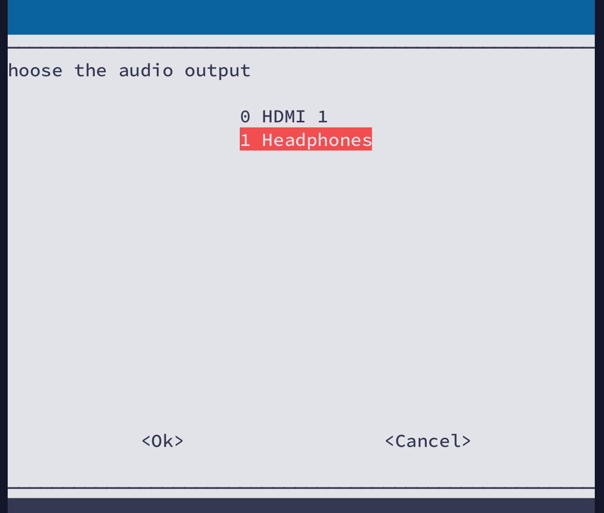
this opens a menu to set the default audio output, you want to select "System Options", "Audio", "Headphones". After the confirmation page, you can cancel -> back -> finish.
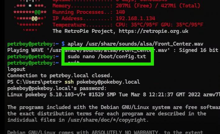
> You can reboot with the "sudo reboot" command or just powerdown and turn the pi back in, remember to SSH back in. From here, you can test the audio by temporarily wiring up the speaker directly to GPIO 13 and GND, then run the following line to play a test audio.
aplay /usr/share/sounds/alsa/Front_Center.wav
GPIO Buttons
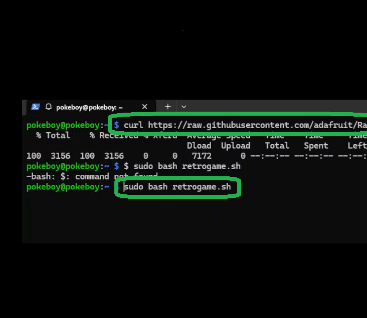
> We will be using retrogame to set our GPIO pins as button inputs. Run the following two lines:
curl https://raw.githubusercontent.com/adafruit/Raspberry-Pi-Installer-Scripts/master/retrogame.sh > retrogame.sh
sudo bash retrogame.sh
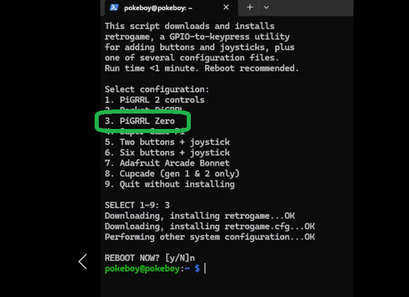
You will be prompted to install a template, I used PiGRRL Zero, but either should be fine. You don't have to reboot yet.
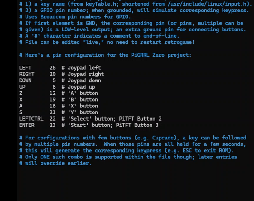
> Open the config file with the line below, and set the GPIO pins to the keybinds seen in the final photo below, there will be unused keybinds that should be deleted from the template so they don't interfere with other GPIO pins, open the photo in another tab if necessary. save, exit, and reboot. (CTRL+X), (sudo reboot).
sudo nano /boot/retrogame.cfg
sudo reboot
> You can now test the buttons by using a jumper wire to short a GPIO pin to GND, emulation station should respond, you can further configure the buttons there.
Roms
> I probably can't tell you how you can go onto reddit r/roms and pick one of those websites in the info tab on the right under the rules to download games... so I won't
> What I can do is provide a link to WinSCP so you can drag and drop files from your computer to the Pi over SSH
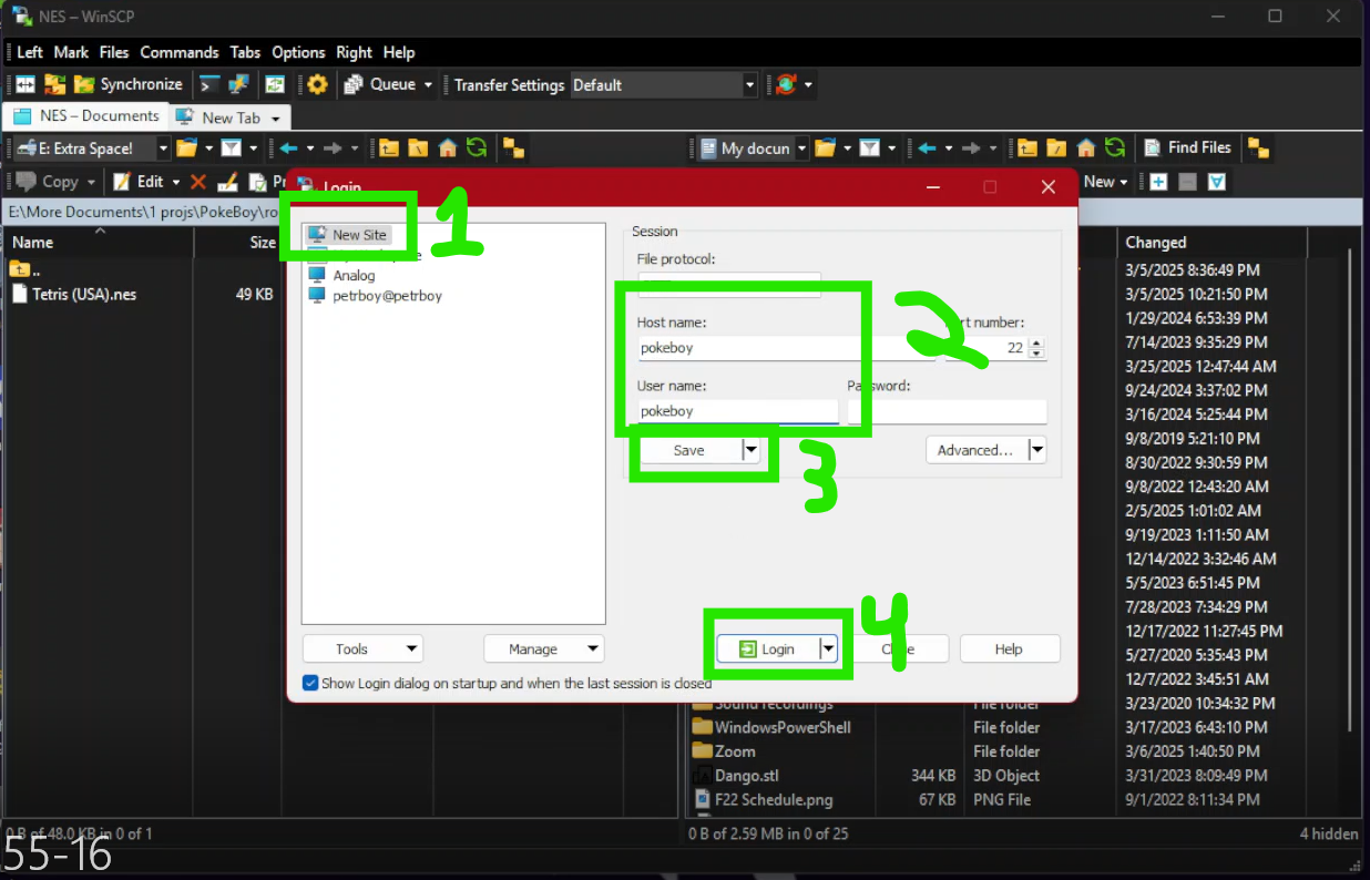
> Launch WinSCP, select New Site, then enter pokeboy for both Host name and User name, then save and ok.
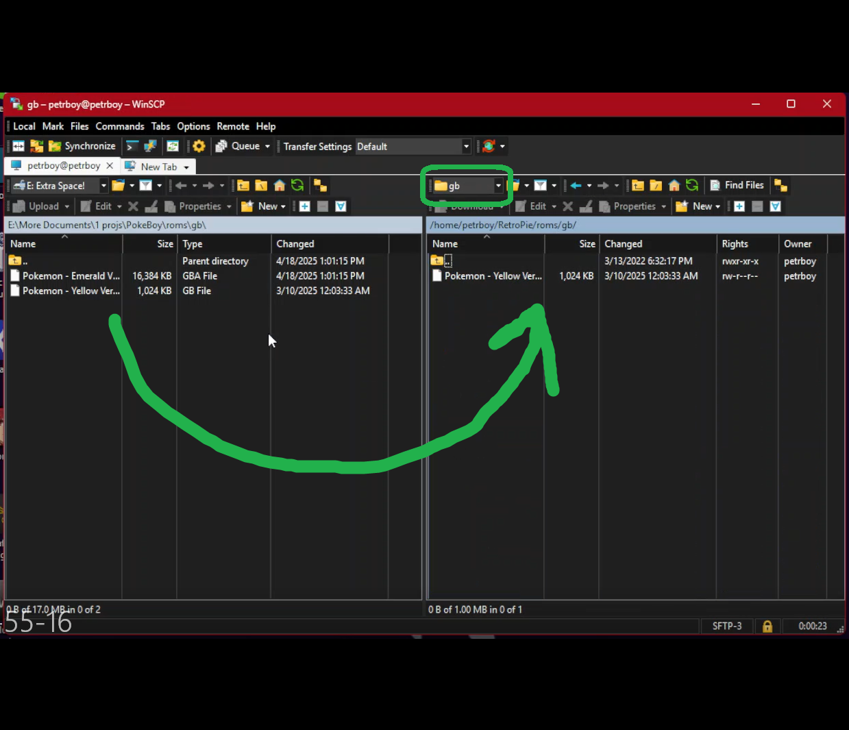
> Click login and enter the password to access the Pi. The left side should be your computer and the right should be the pokeboy. On the left, navigate to where your games are. Then on the right, go to Retropie -> Roms then select the console you want to emulate. Drag and drop the game from left to right and reboot after its done downloading.
PCB assembly
> Now that we've tested and ensured that the Pi actually works... treat yourself to a nice dinner, you got through the hard part.
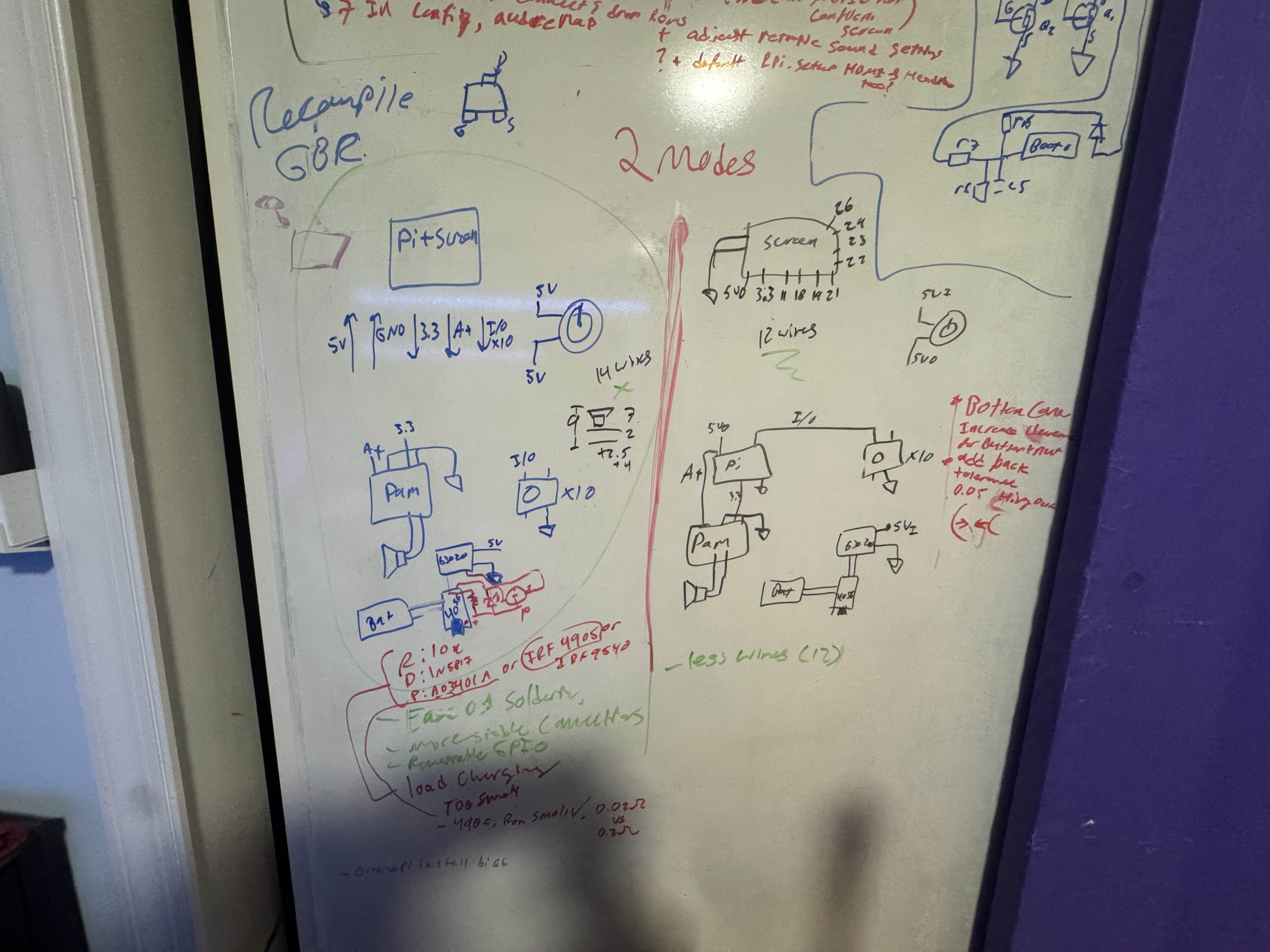
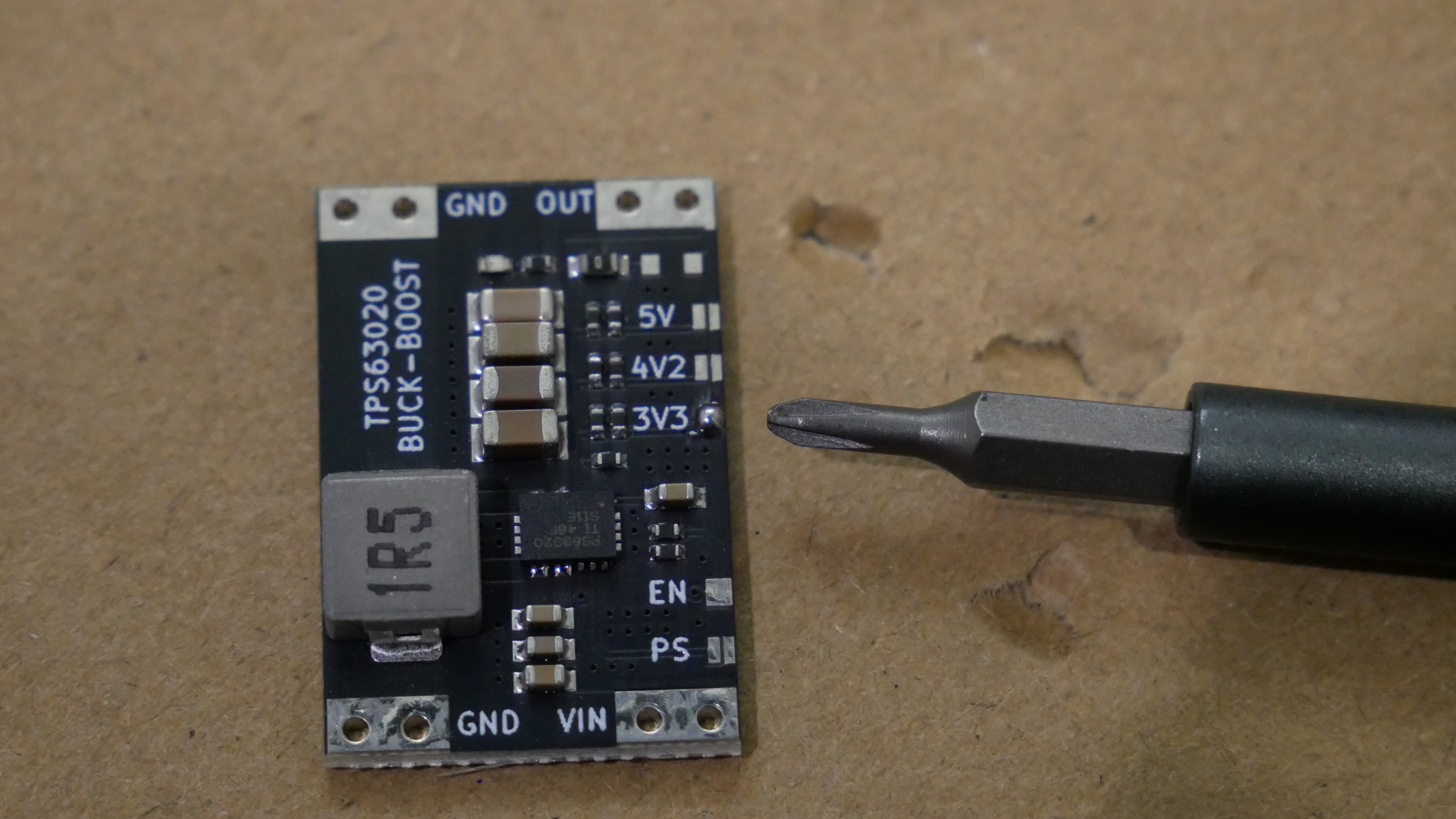
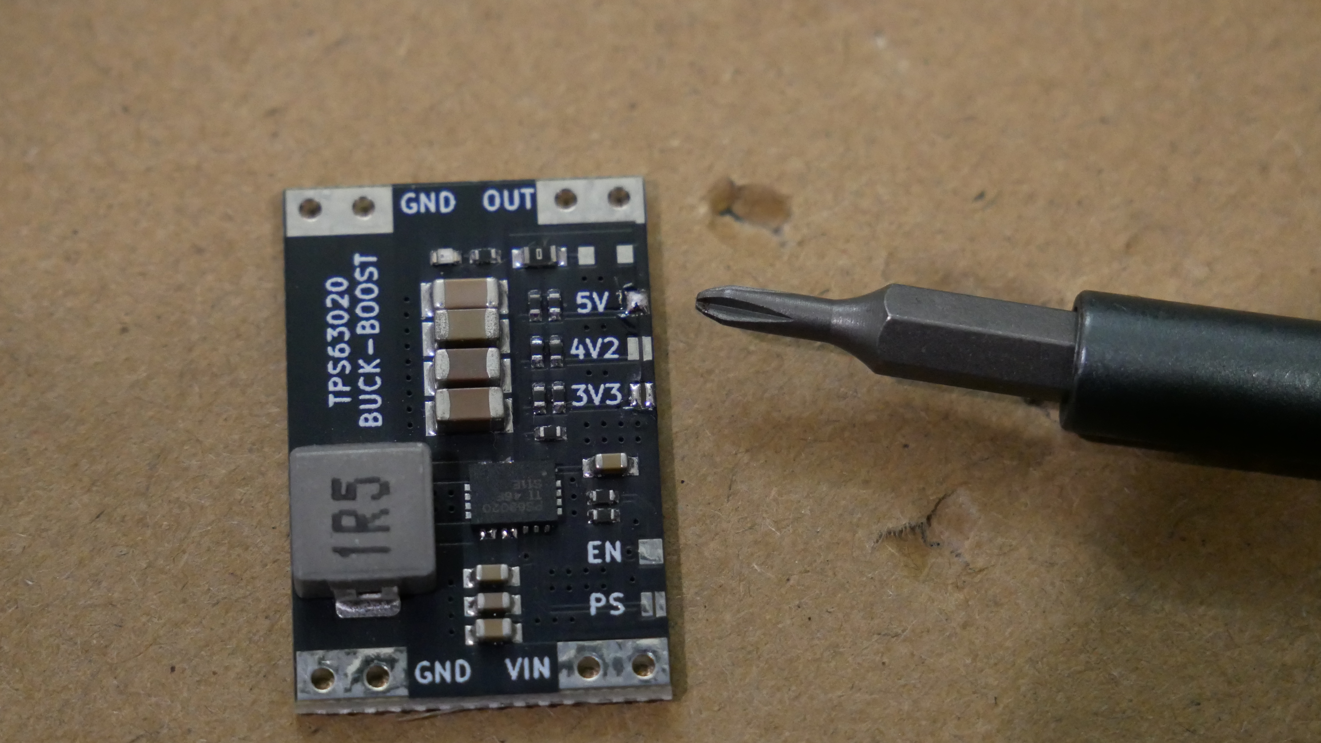
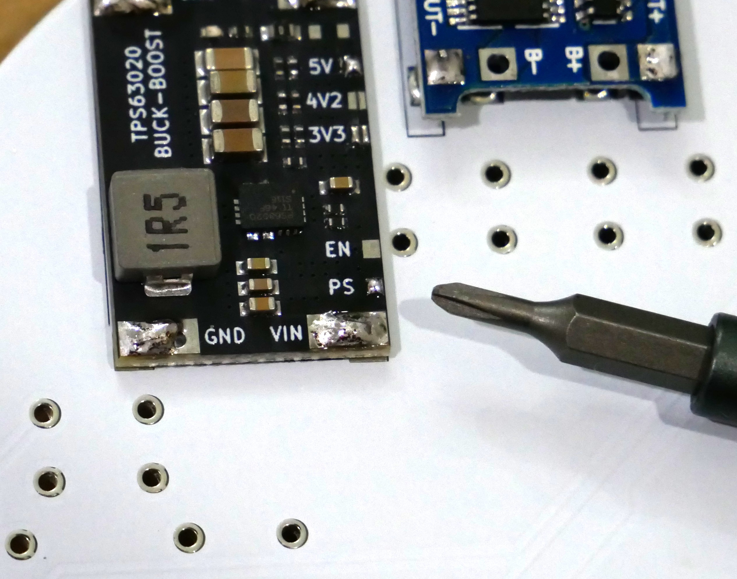
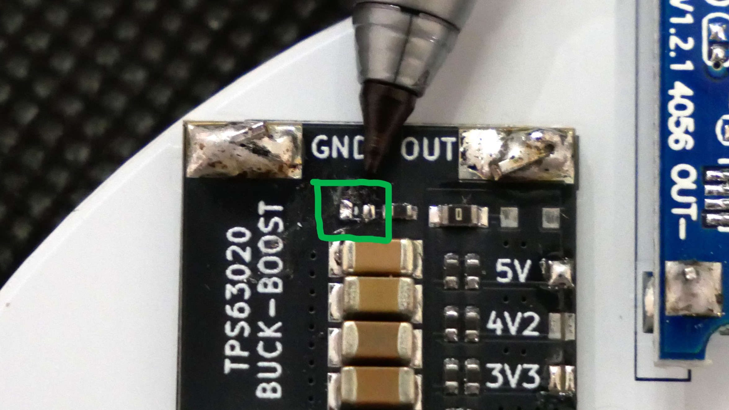
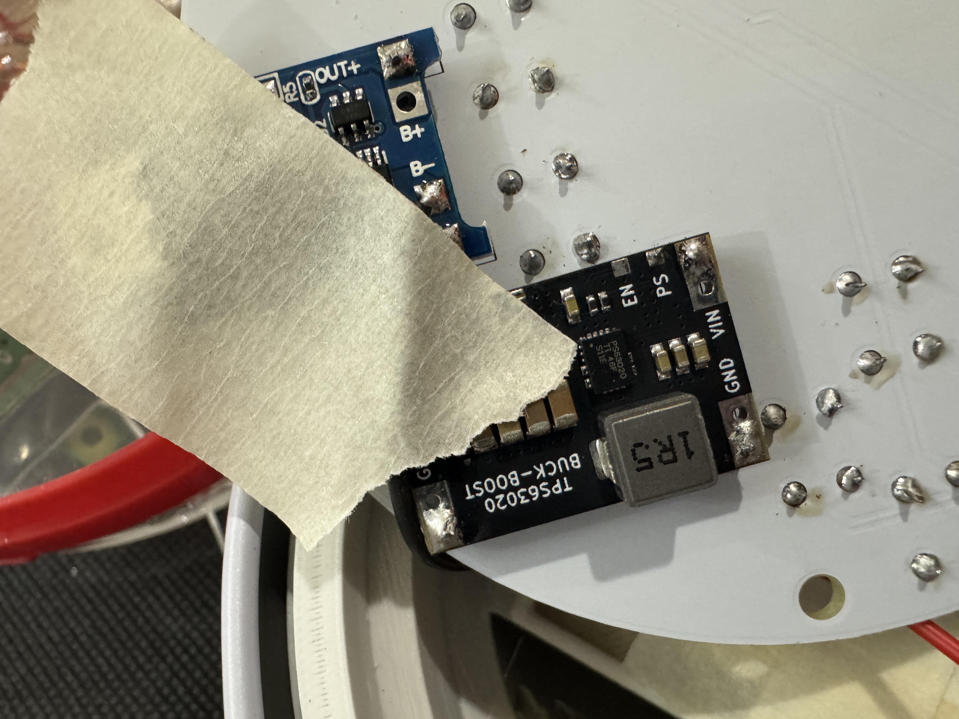
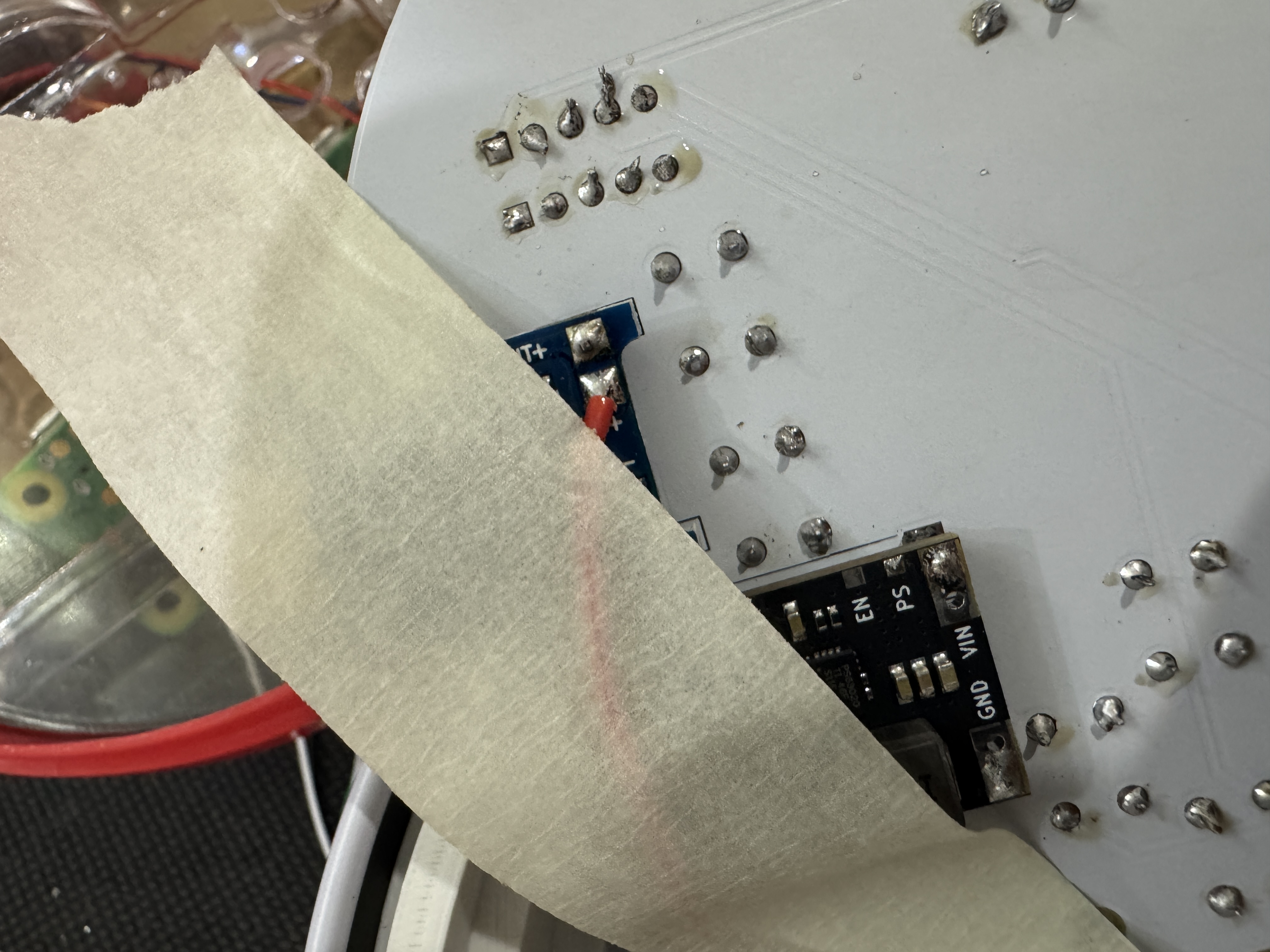
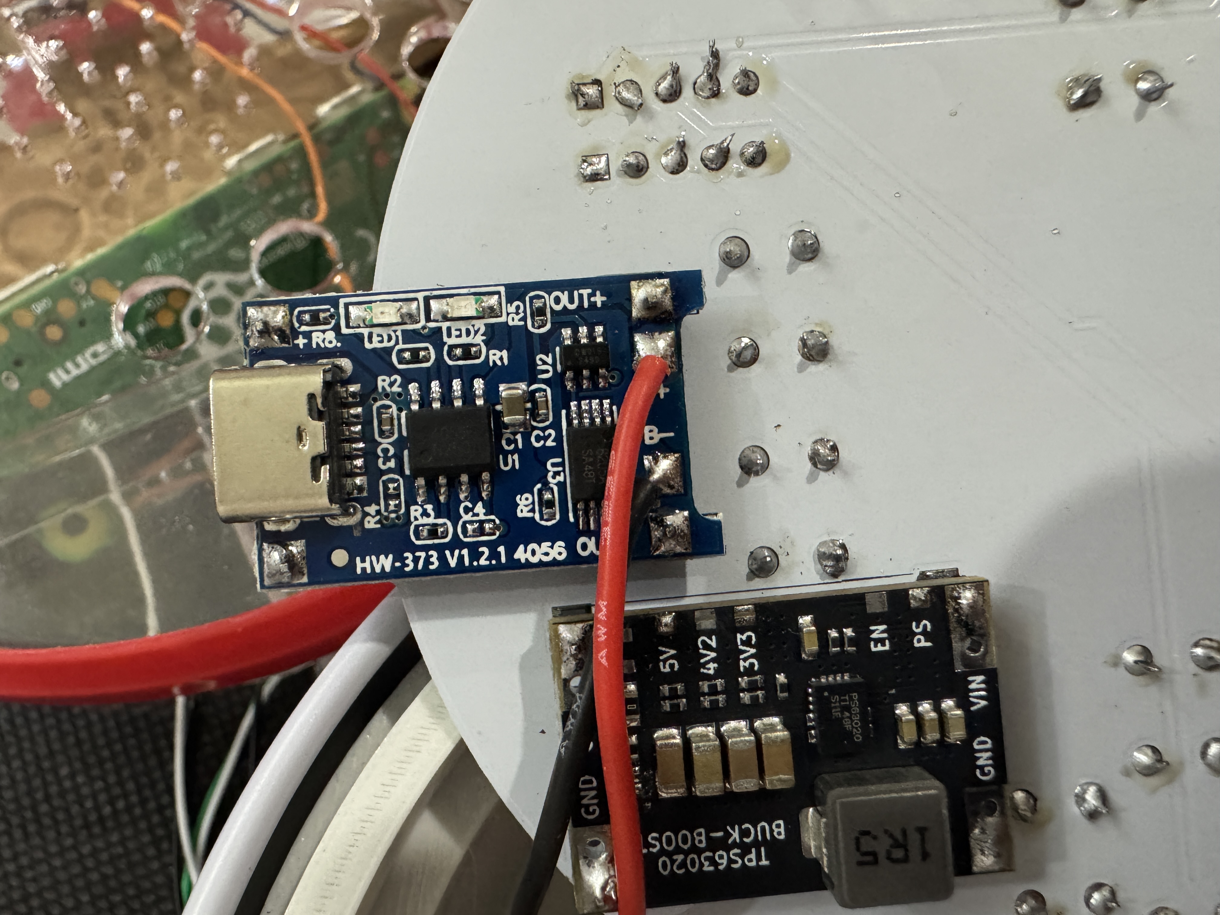
> Before soldering everything together, we need to modify the boost converter first. The unit will usually come with 3.3V on the output by default. Desolder the short where it says 3.3V and short out the pads where it says 5V to set the output to 5V. Then short where it says PS for low power consumption when not in use. Lastly, there is an LED on this unit, apply a good amount of solder and remove it to reduce unnecessary power consuption, besure that there is no short there when done.
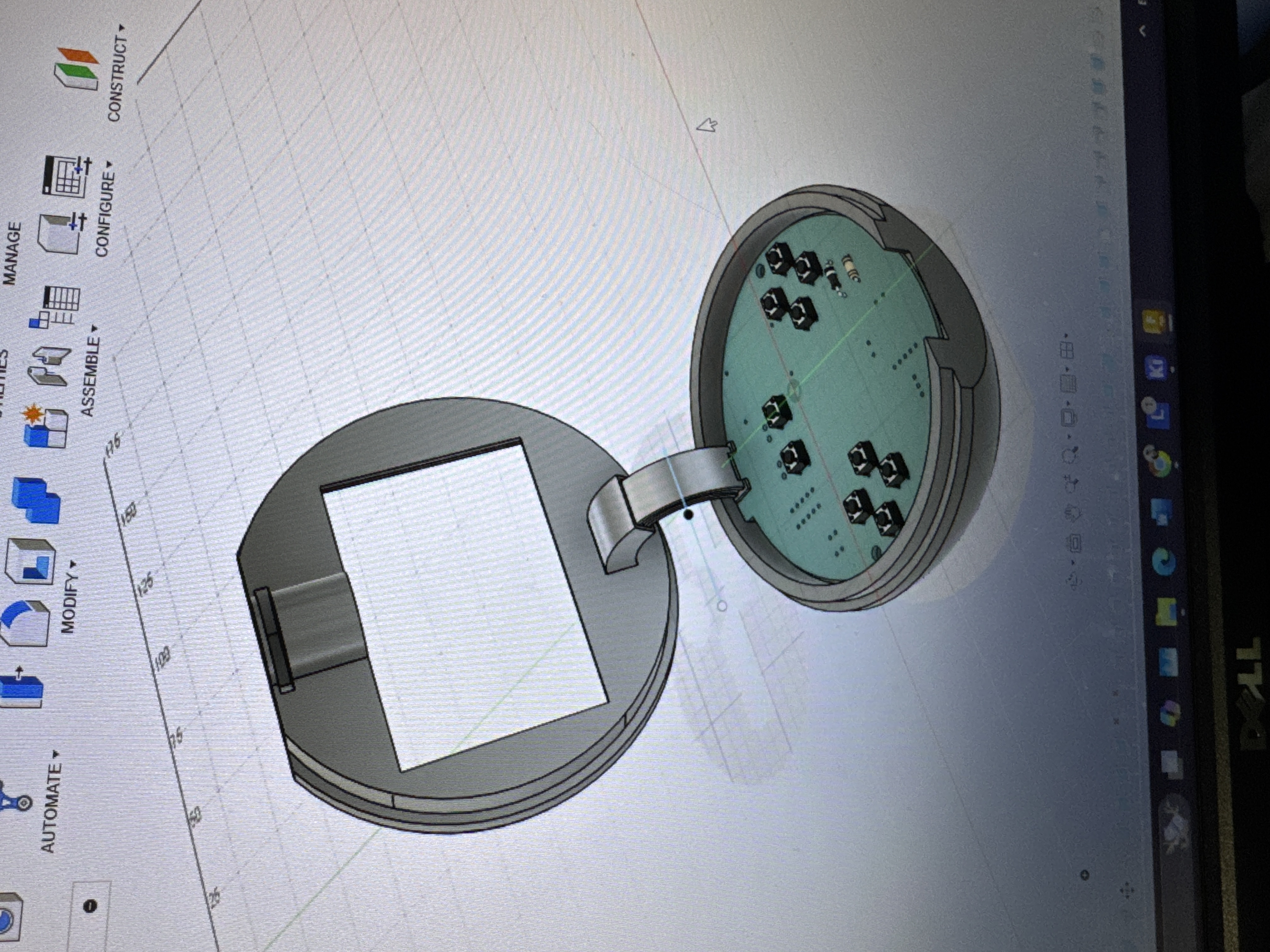
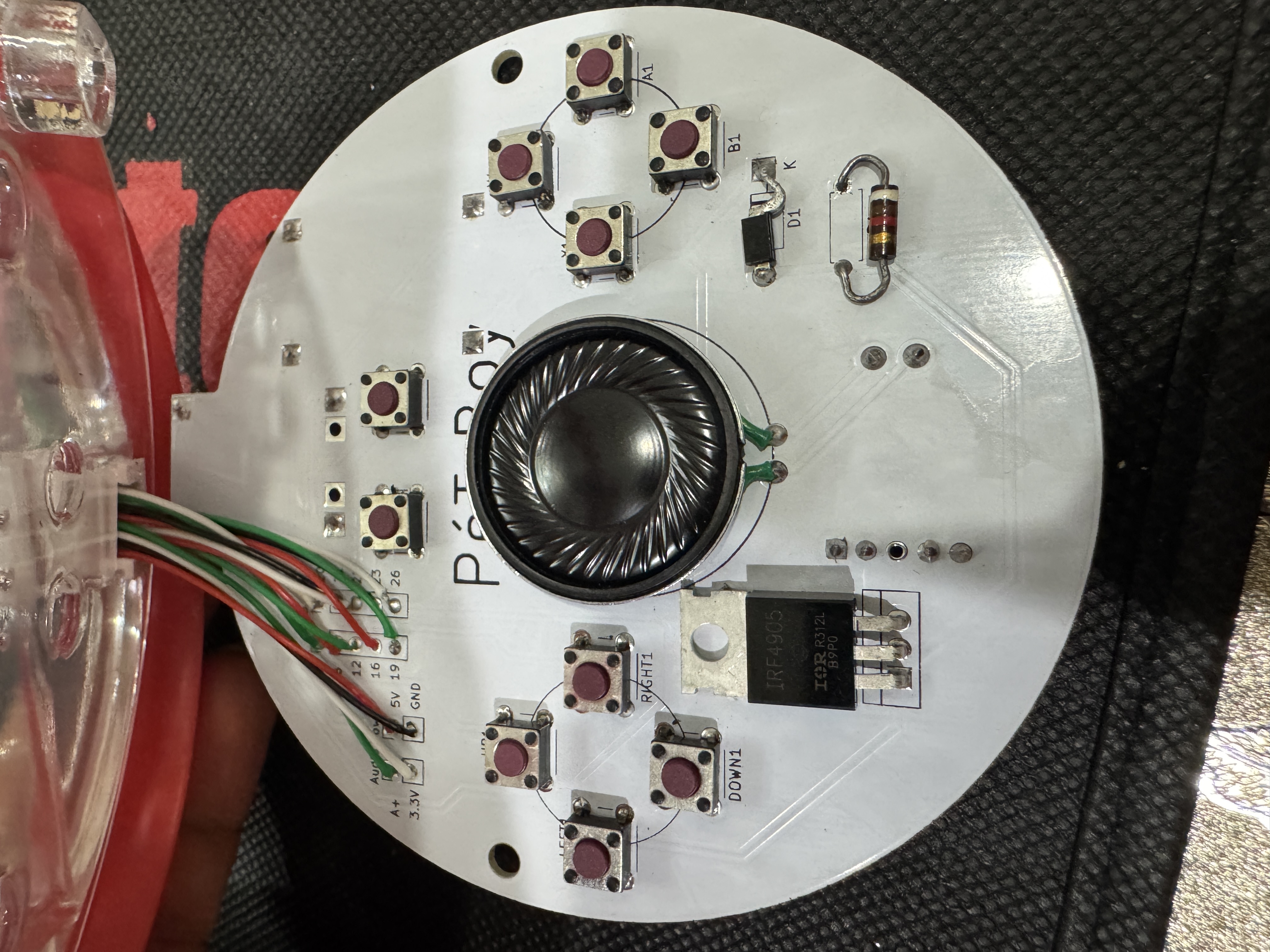
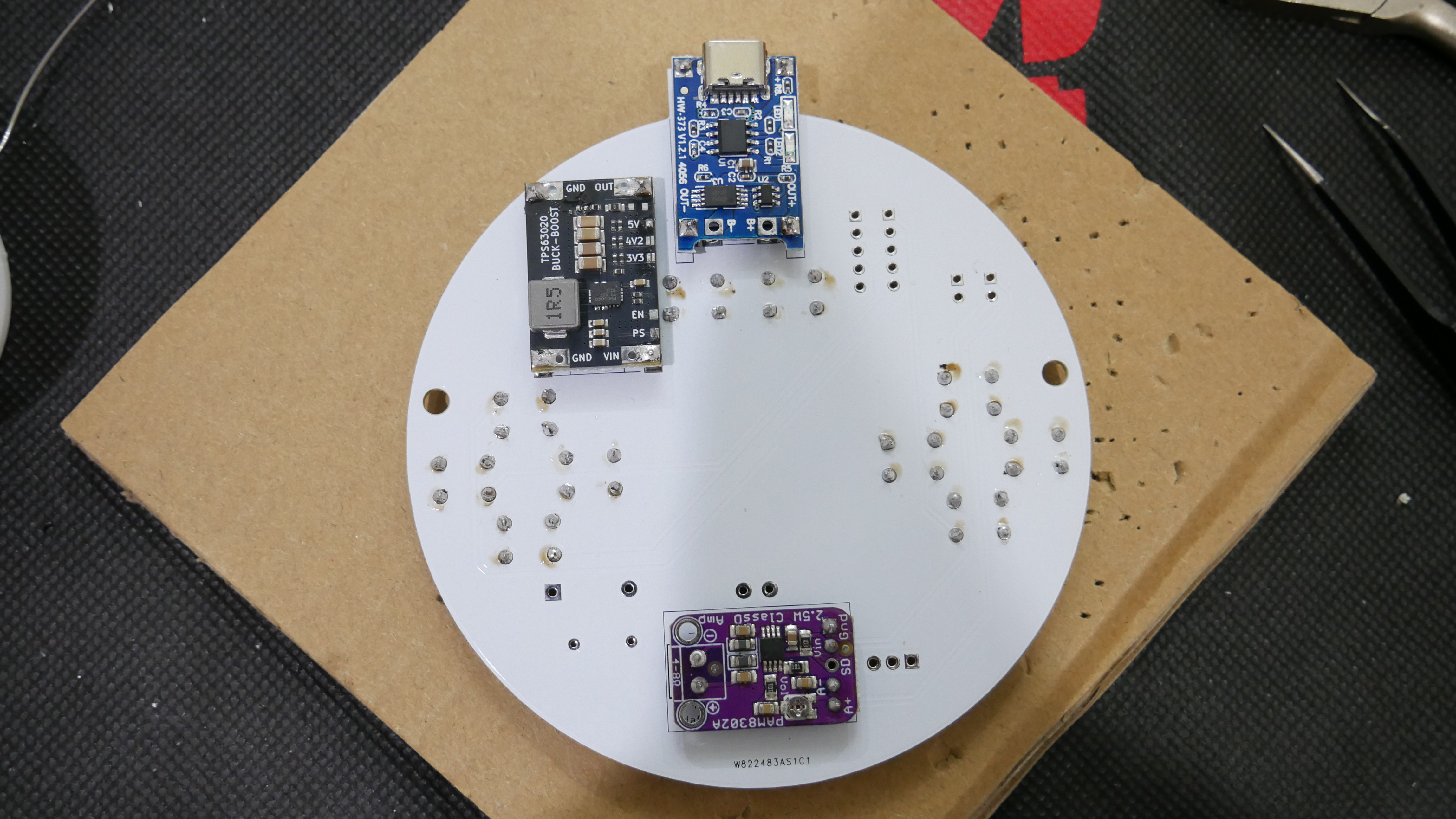
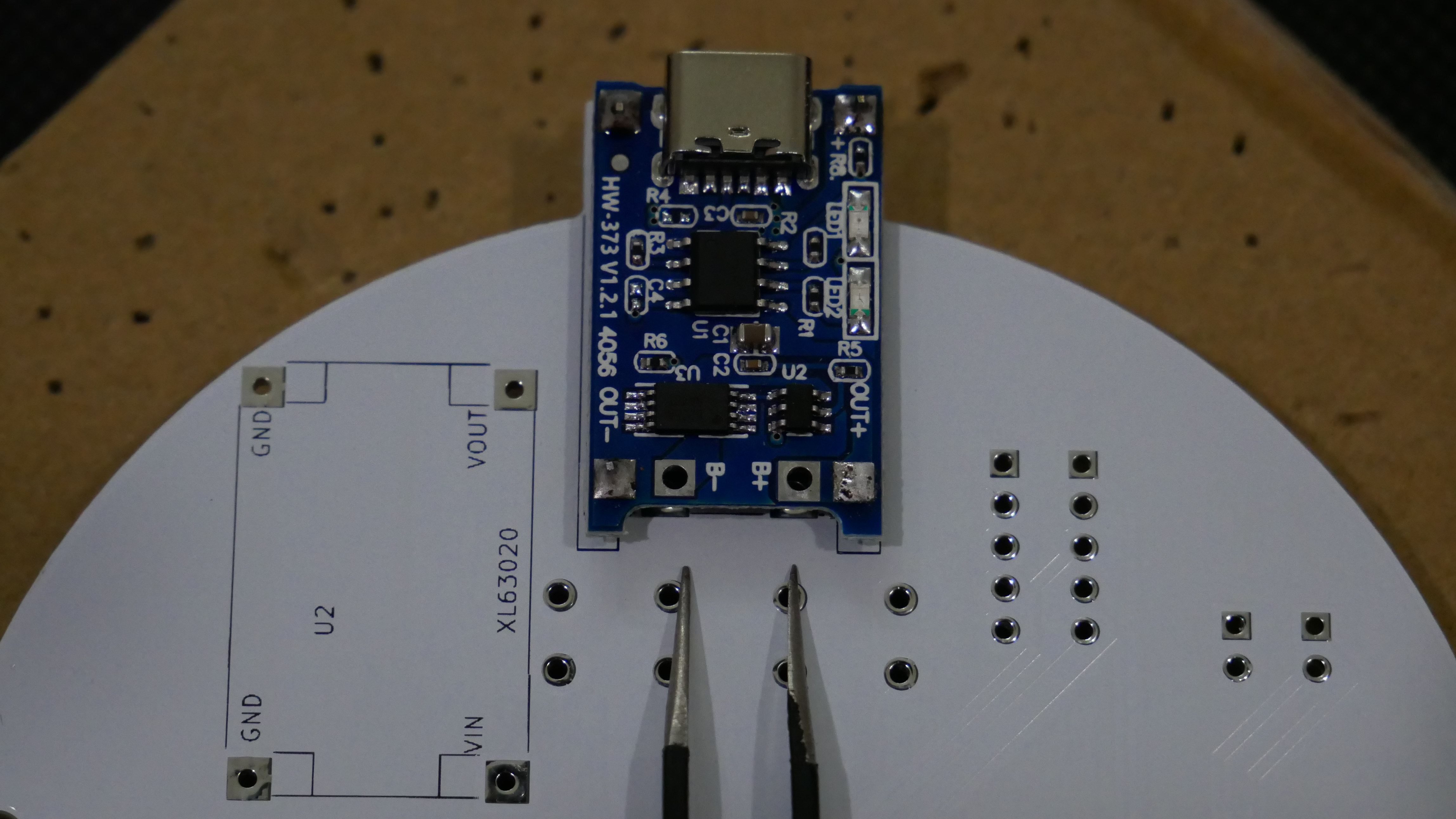
> Solder the headers onto the boost converter, amplifier and battery charging module. Leave the two inner pinouts of the battery charger vacant to apply the battery later (see pic 2 below). Then solder the modules to the board along with the buttons, P-Mos, 10k resistor, and diode (I recommend making sure the P-Mos legs, G-D-S, match the pinout on the PCB)
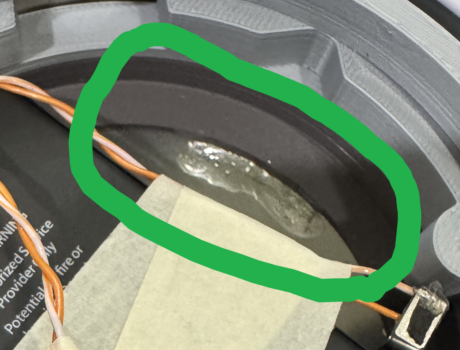
> Solder the speaker down within the circle drawn on the PCB, if you use short CAT5 wires, it will be thick enough to stay down without double sided tape.
Pokéball Part 1
> Now we will work on modifying the Pokéball
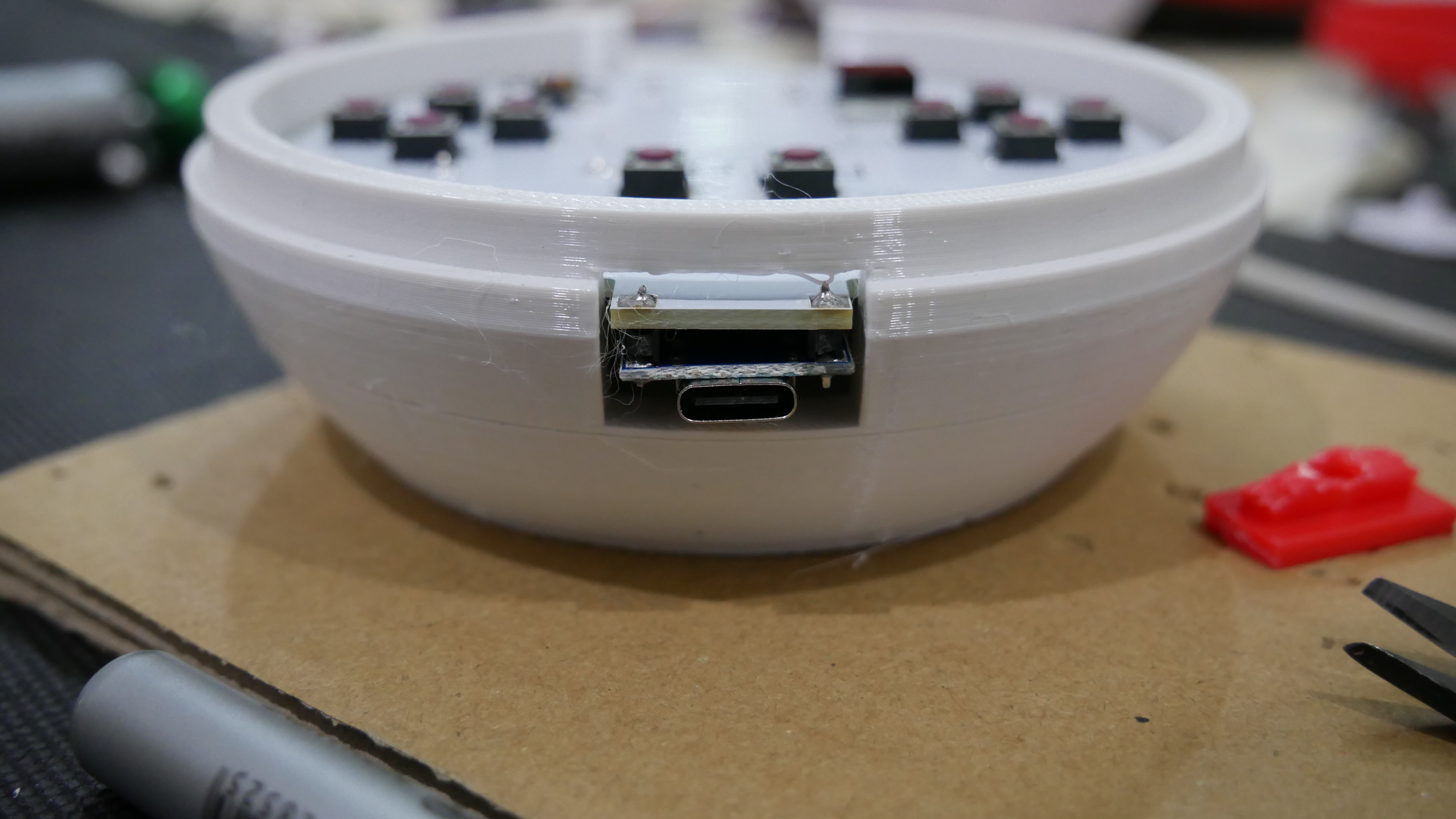
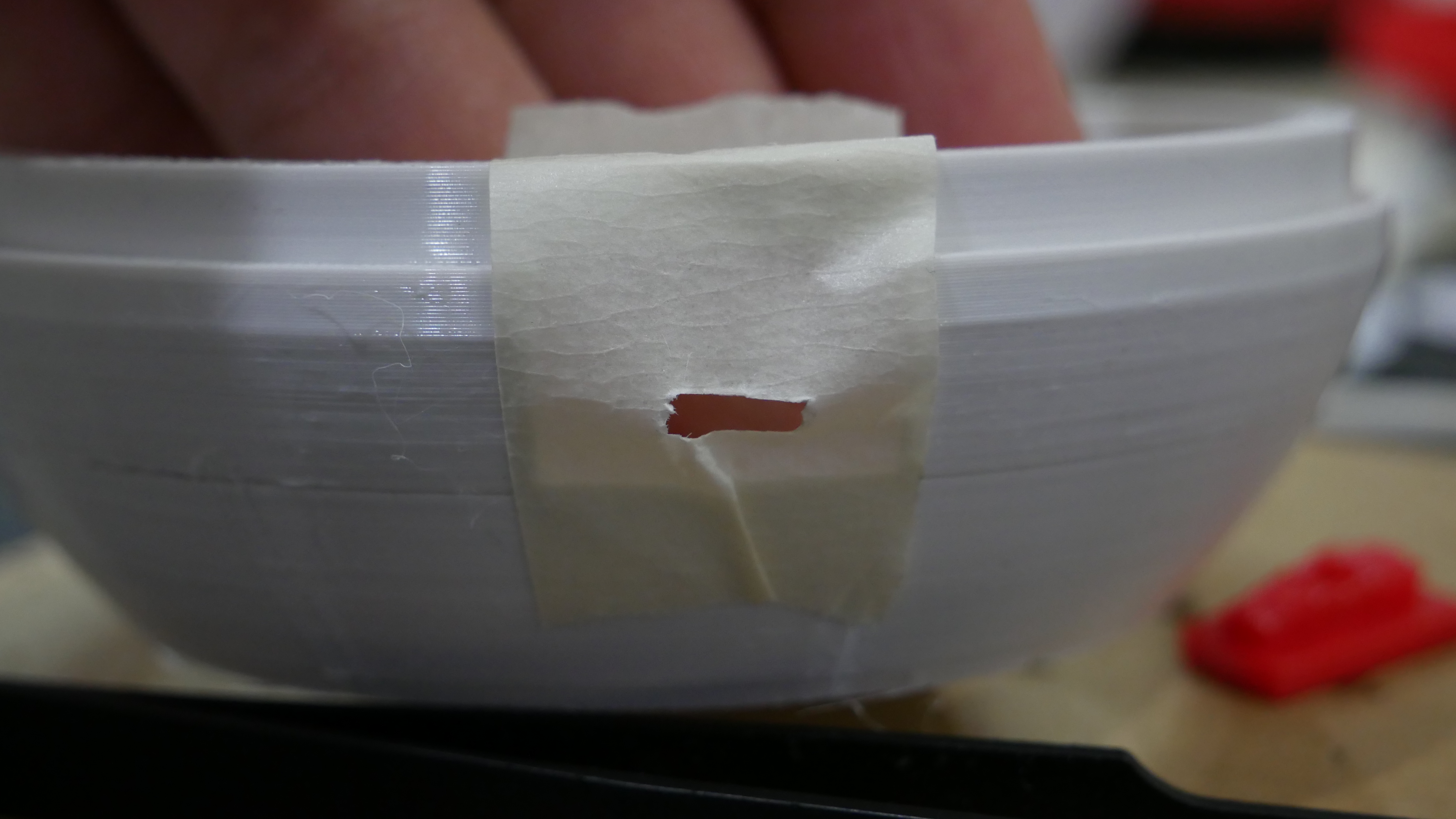
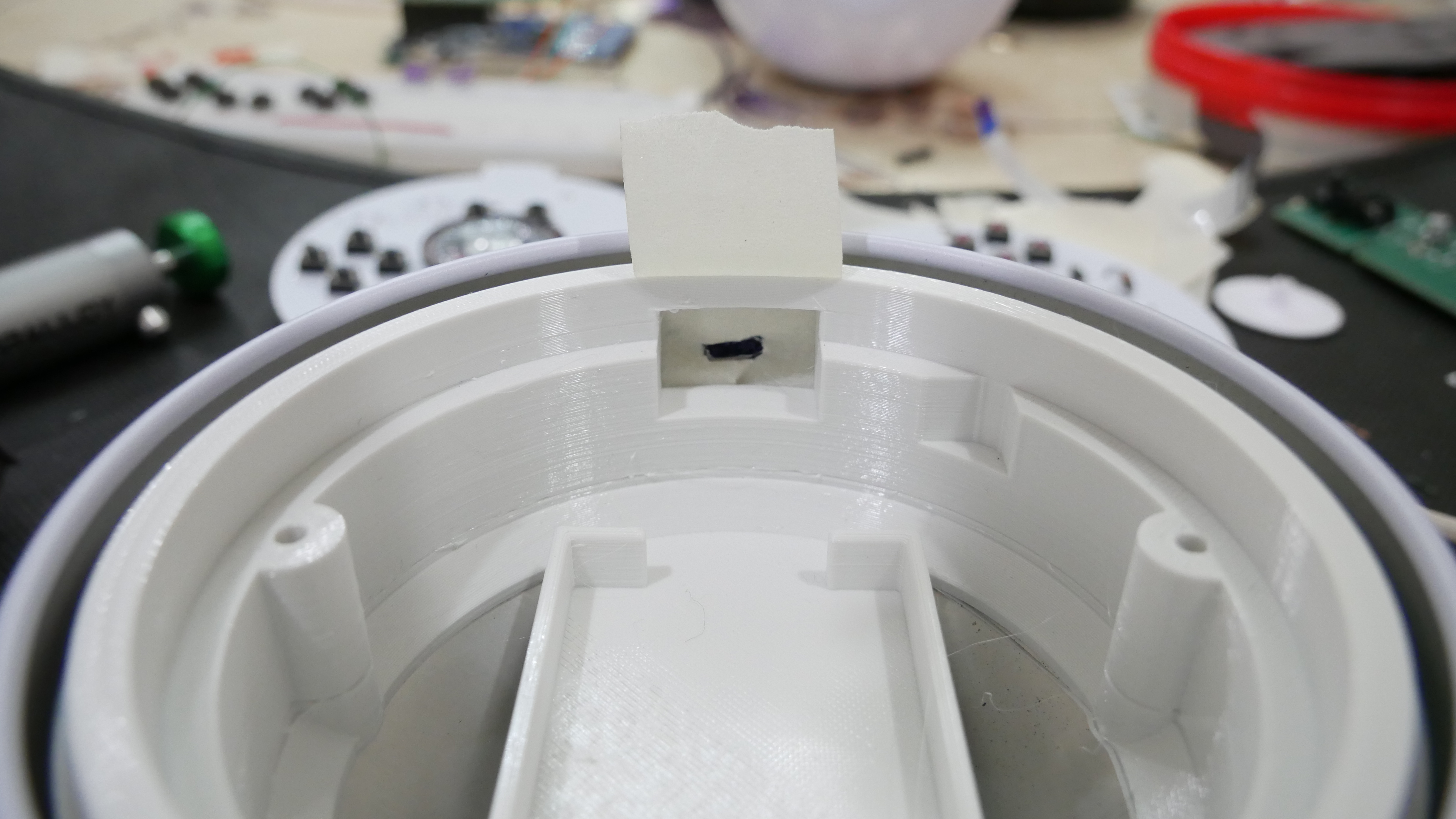
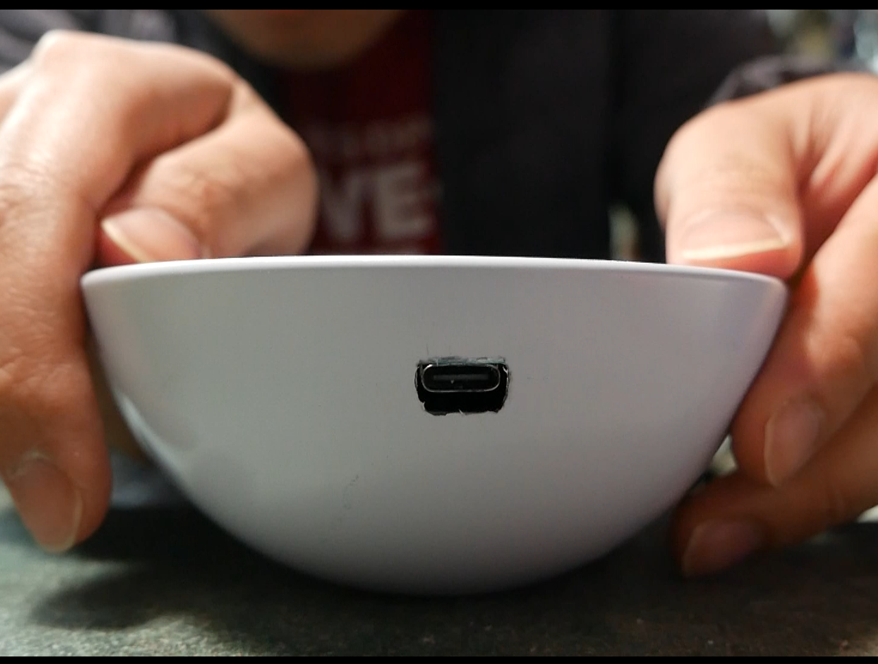
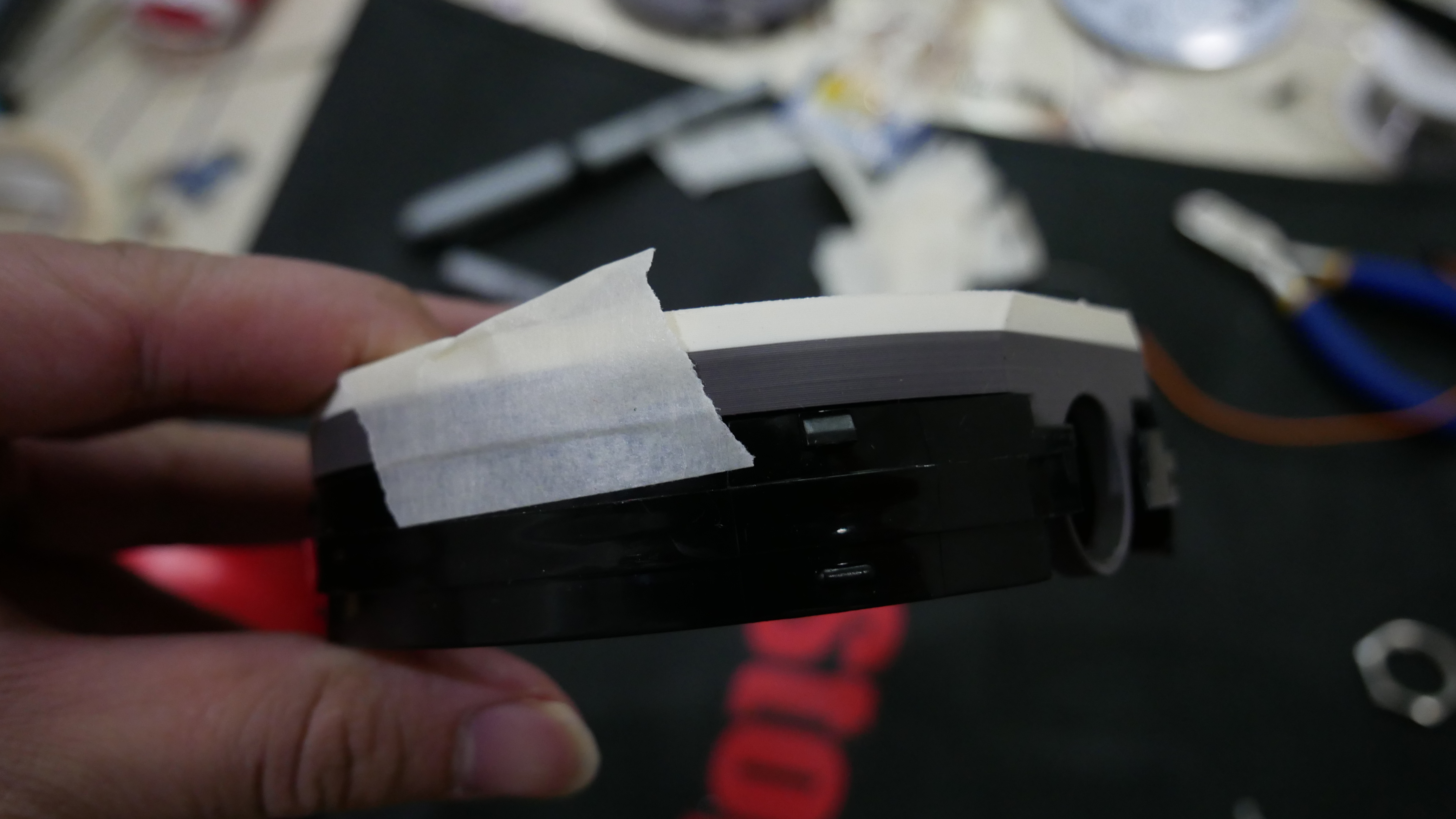
> First, open all of your packs and be sad that you didn't get the Moonbreon... then grab the 3D print for the bottom and place the PCB assembly inside. Grab some scotch tape and apply it to the 3D print overtop the hole where charger is. Using whatever sharp object you have, make a hole where the USB-C port is then remove the PCB. Now place the 3D part into the bottom half of the pokeball, line it up as best you can to be level and centered to the lip of the ball, use the 3D-printed face plate to help. Once in position, use a marker to mark where the USB-C port would be on the ball.
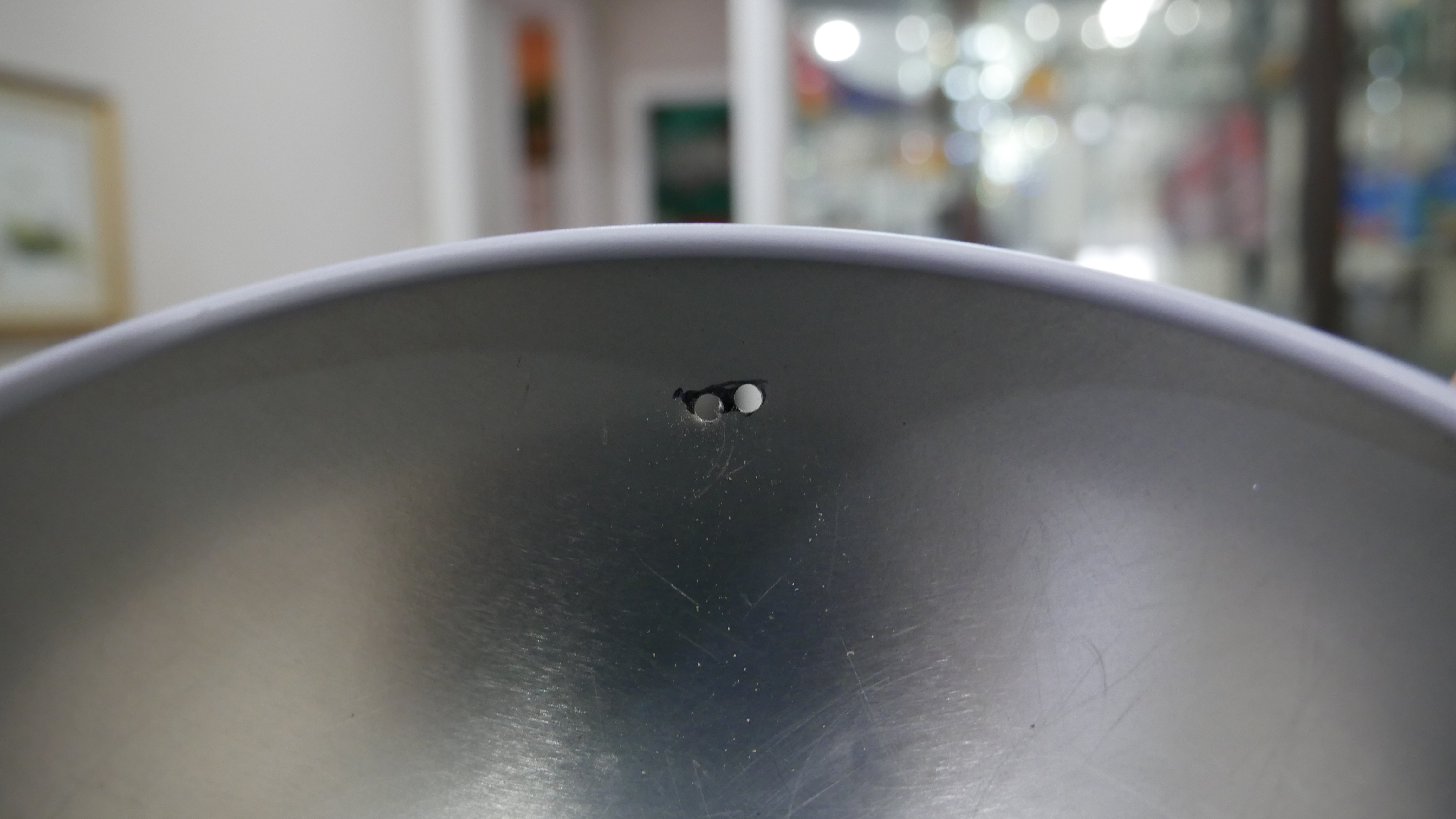
> Using a drill, make one or two holes where the marking was, then use some cheap hobby files from harbor freights to shape the hole, use the bottom 3D part and PCB to periodically check the fit, you want about a 1-2mm clearance all around the port.
Pokéball Part 2
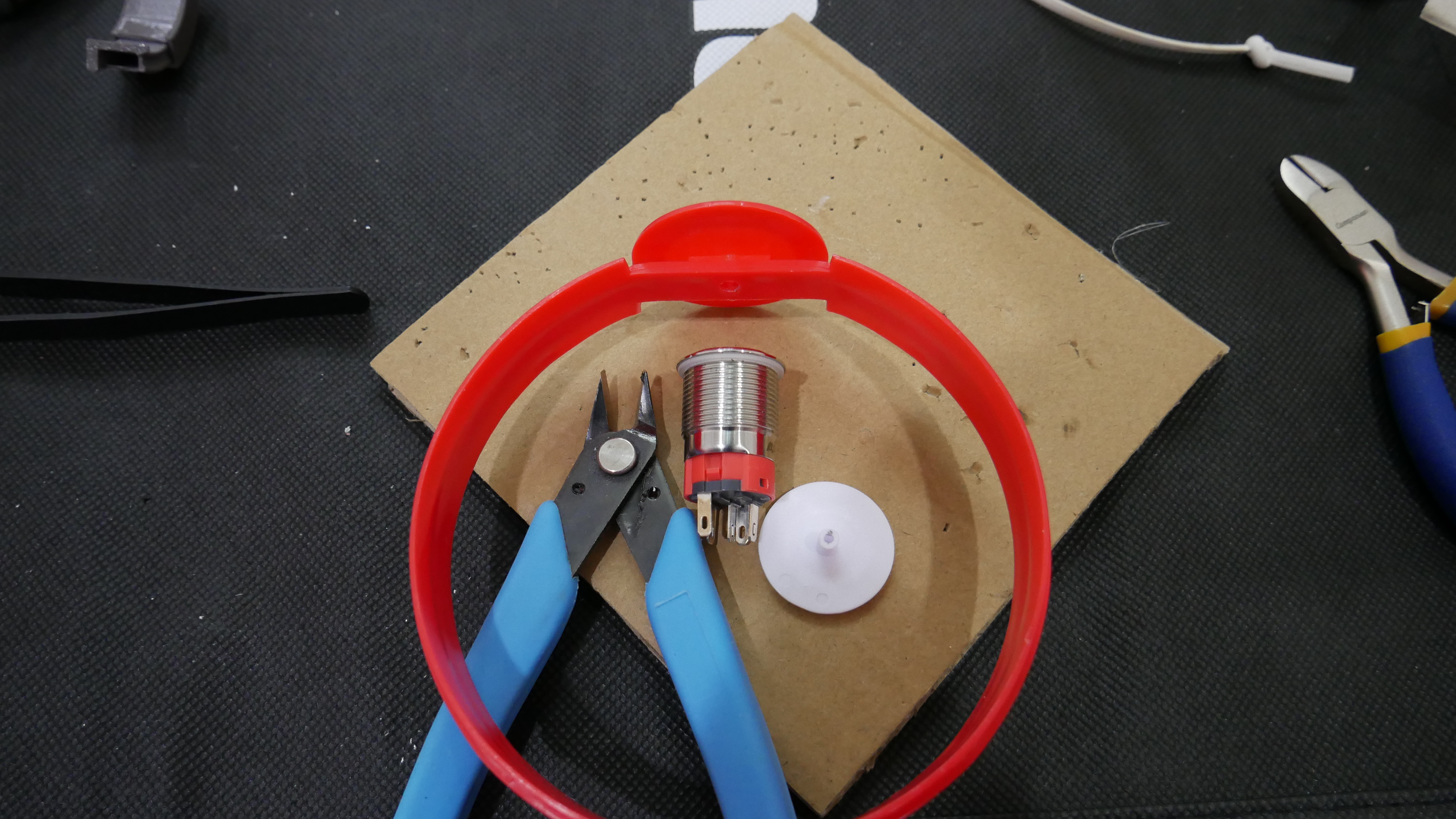
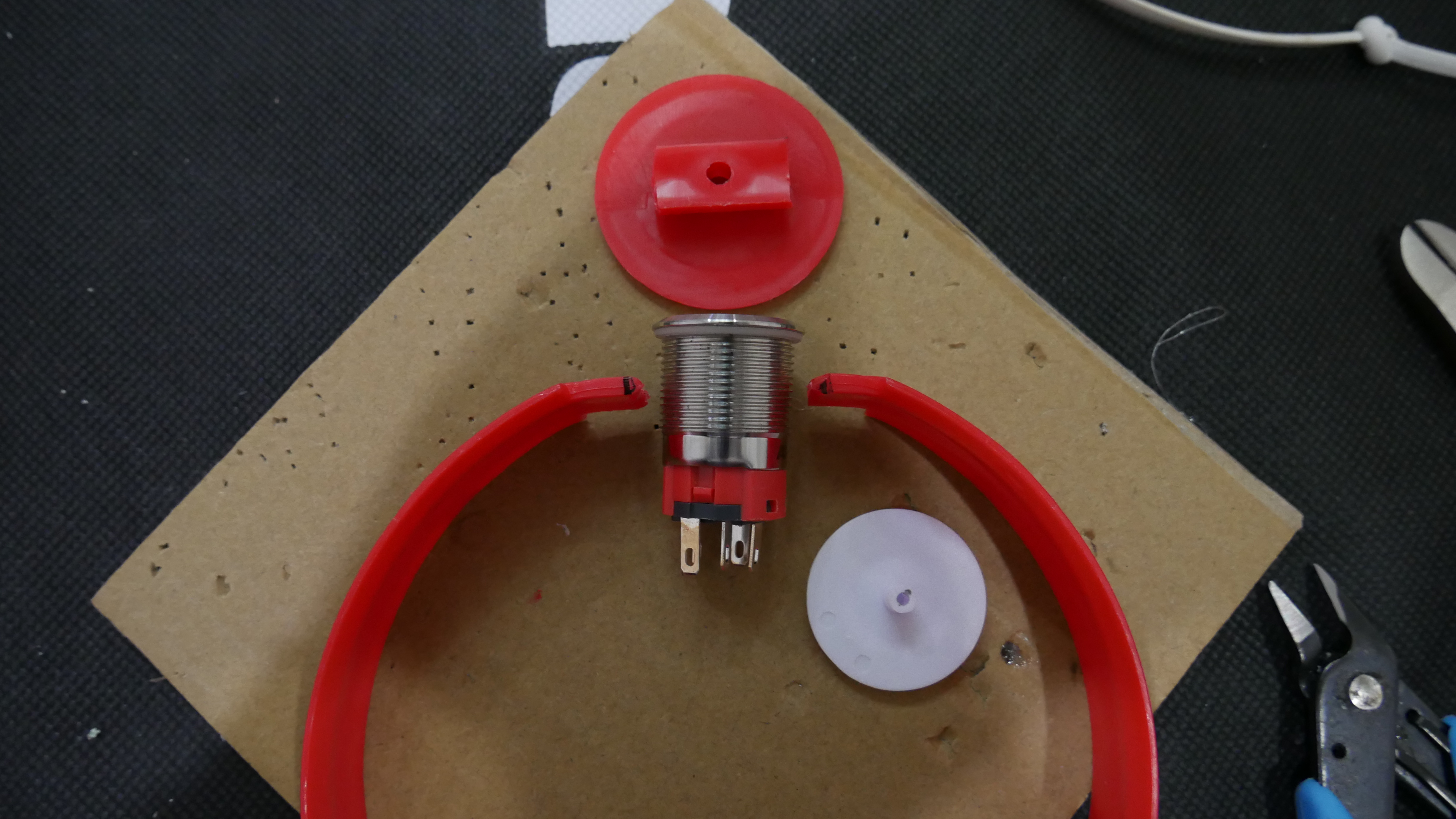
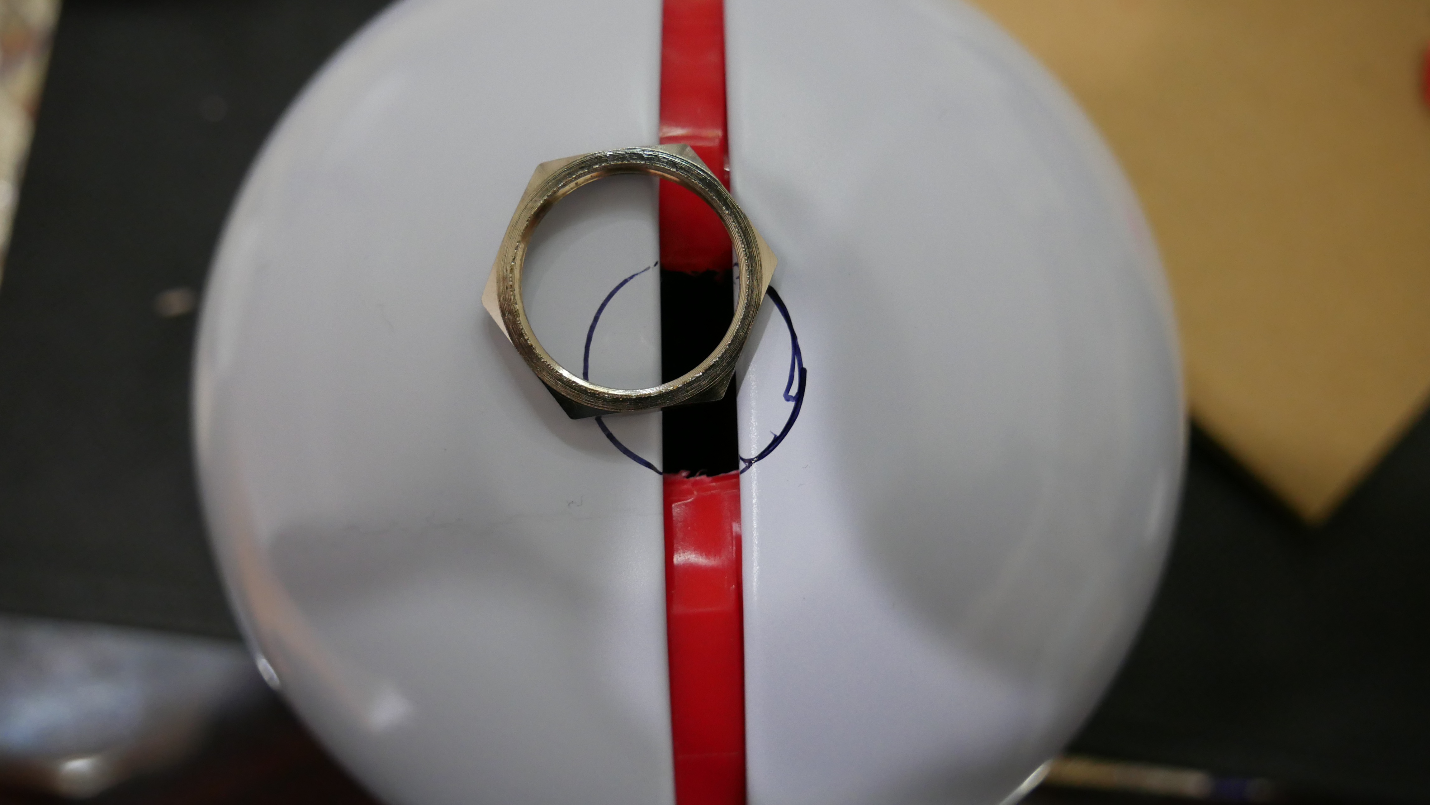
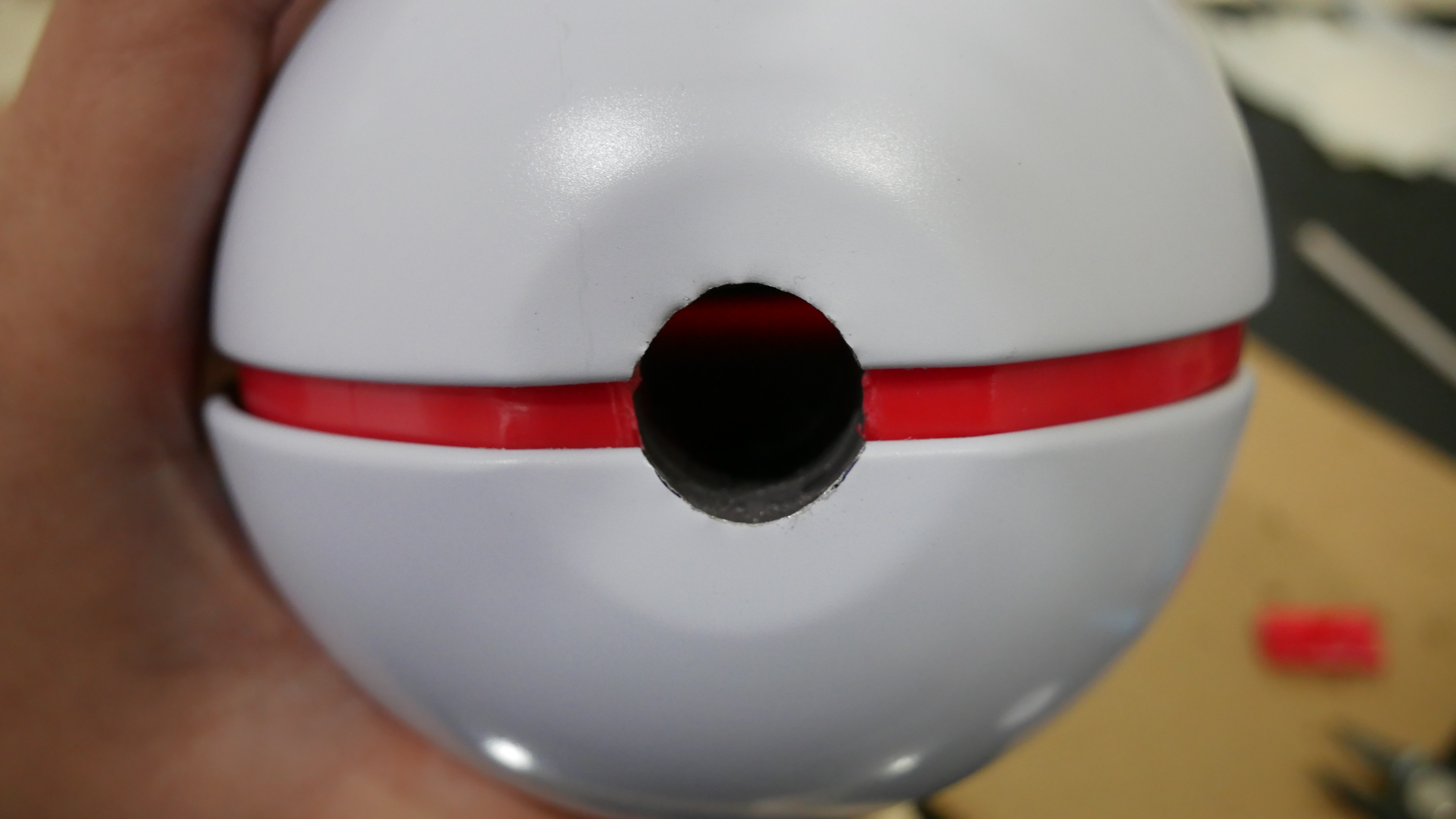
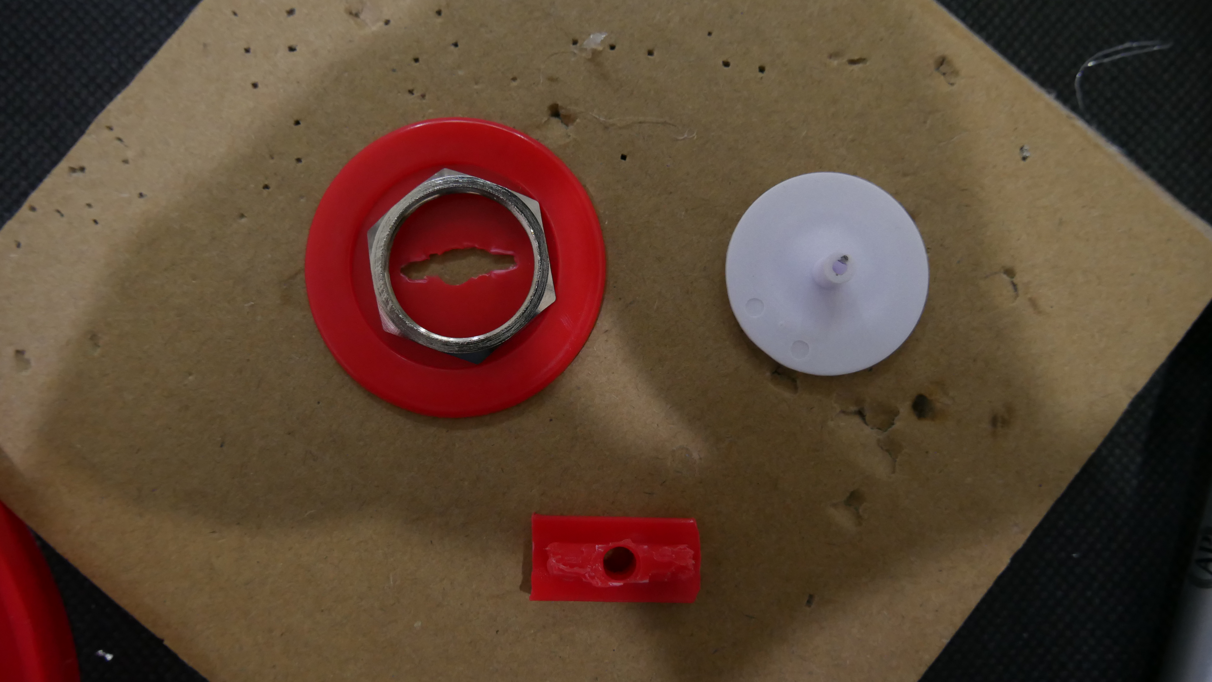
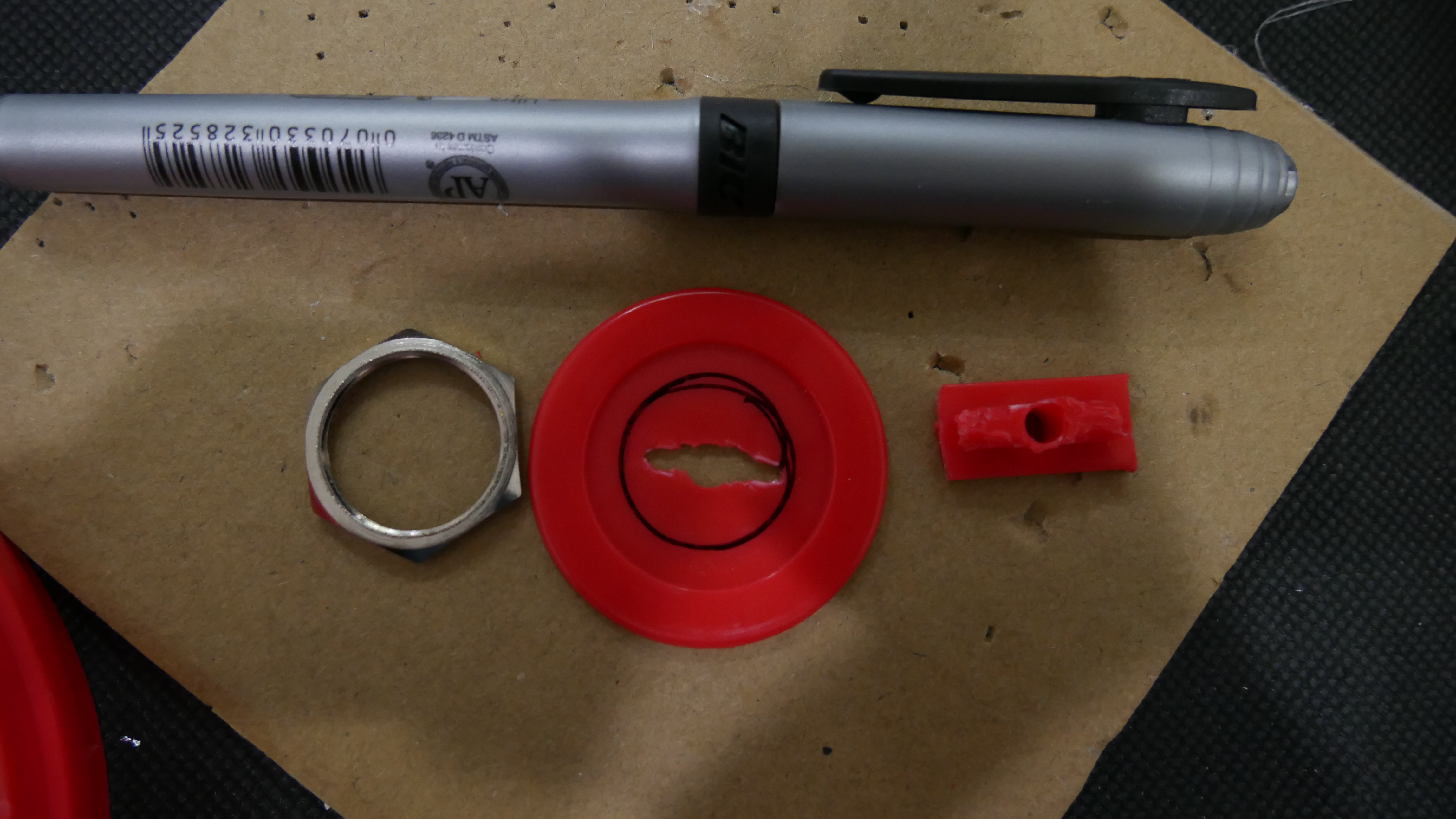
> Next, pop out the pokéball's ring and cut the faux button off, use the power button as a reference for how wide you should make the cut. Optionally, you can cut off the round nubs of the ring so the ball can close smoother, but I found that it wasn't really necessary. Tape the ring to the top 3D printed part so that the ring and part is flush. Reassemble the ball, and using the nut of the power button, gauge and mark an outline for the power button. Use a file to... file away material until you reach the line, then periodically check with the power button to make sure that it can slide into the assembled ball easily. It is okay if you grind a bit too much off... just buy a new pokéball... or cover it with the faux button by popping the white piece out, cutting the back nub off, and filing a hole bug enough for the power button.
> Also, be careful when filing... the tin can get sharp... don't ask me how I know
Epoxy/Hot-Glue
> This is slightly flawed. I think the ring of the pokéball is probably made out of some kind of PVC or similar, because the epoxy barely sticks. I tried super glue before but that was worse. Anyway, if you find a way to bond PVC and 3D printed plastic better, let me know, for now...
> I used some dollar store epoxy on the bottom piece first (note this cures fast, mix only what is needed at a time). I spread some of it on the side of the 3D printed part then inserted it into the ball's bottom. I used the PCB and face plate to help center and level the bottom piece as the epoxy cured, then I used some more along the hole inside between the ball and the 3D printed insert.
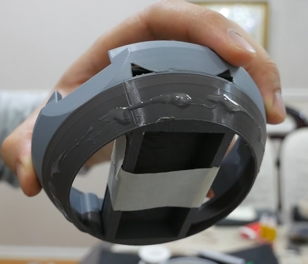
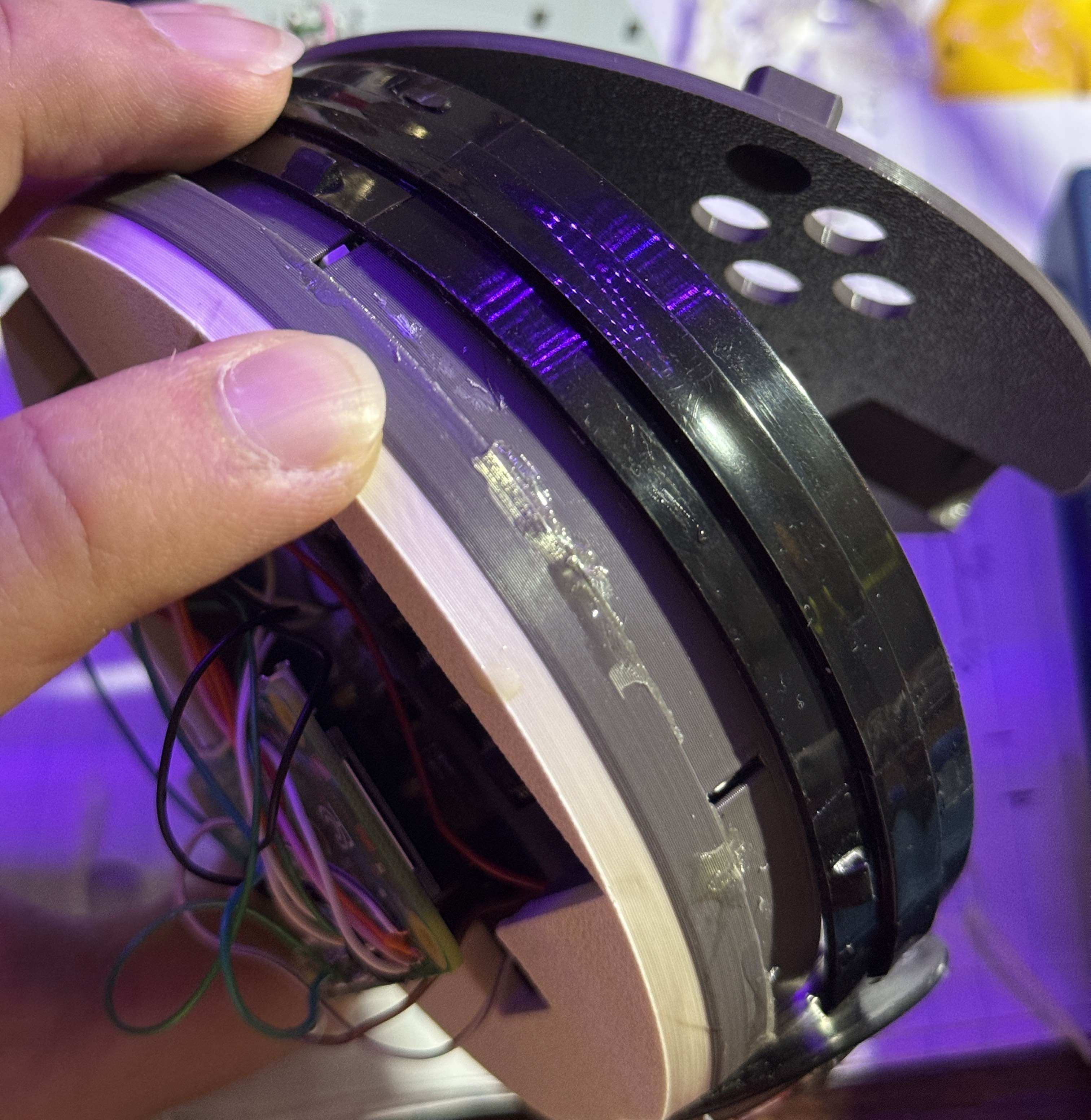
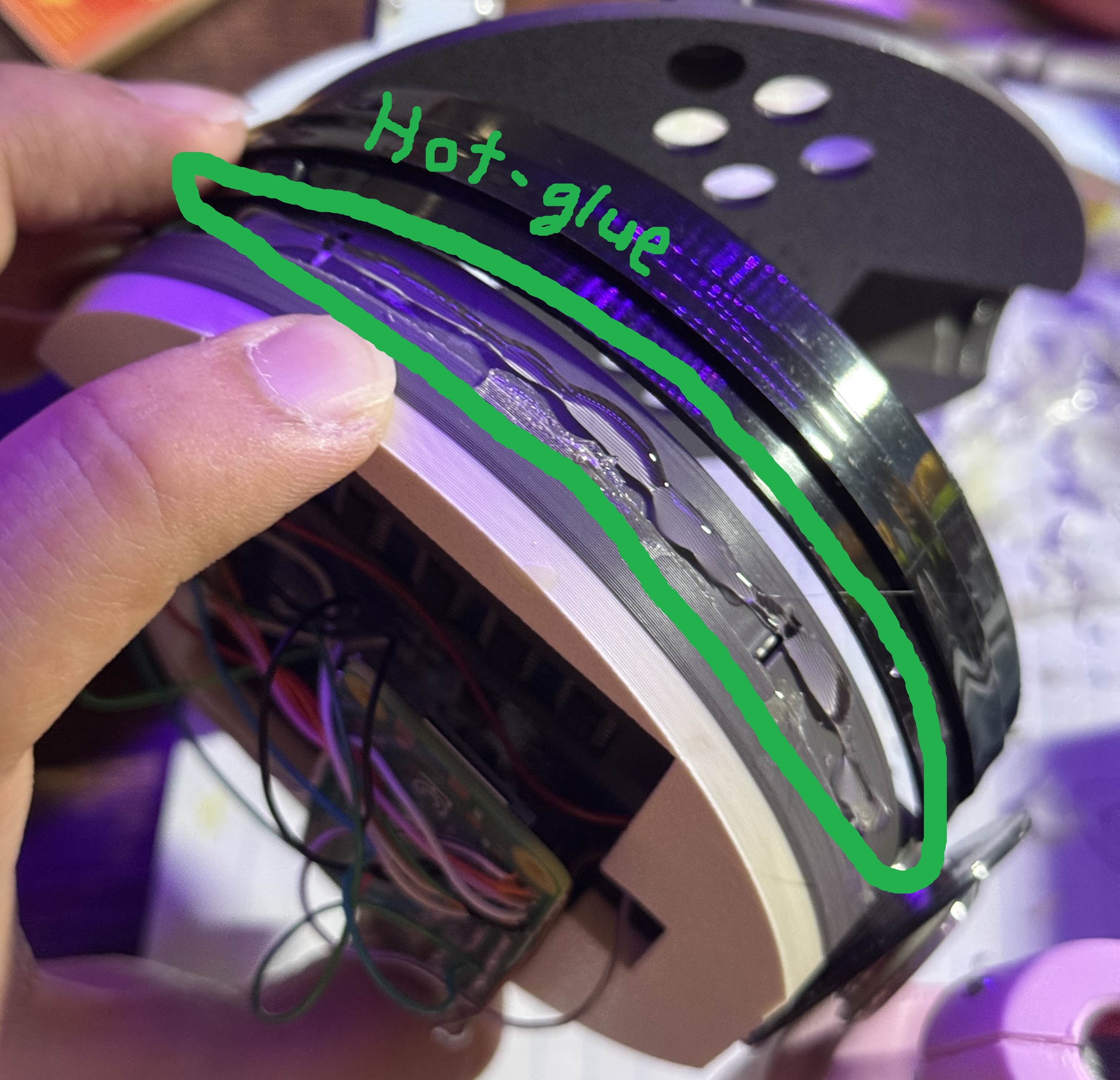
> Edit: I have now found that hot-glue works well in fixing the plastic pokeball ring to the top insert. Apply it in 2 steps. Apply hot-glue to half of the top insert, add the ring, then bend the ring back to glue the other side. Make sure that the ring is flush with the edge of the insert. If you mess up, just peel off the hot-glue and try again. Before, I tried epoxy and it did not stick all that well and took too long to cure, so I think hot-glue is the better option here.
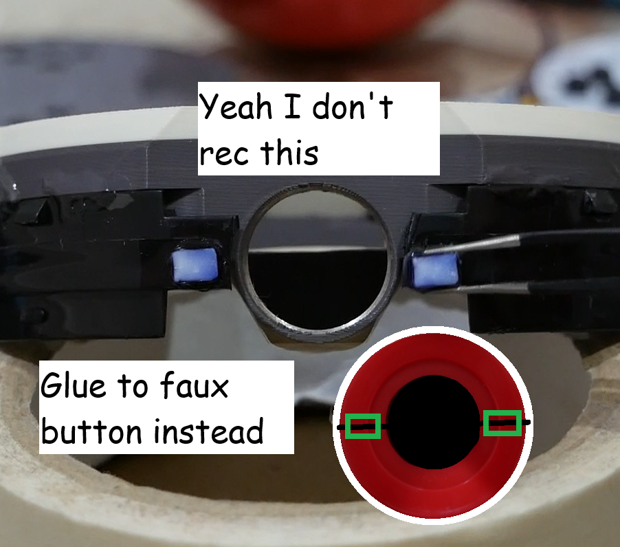
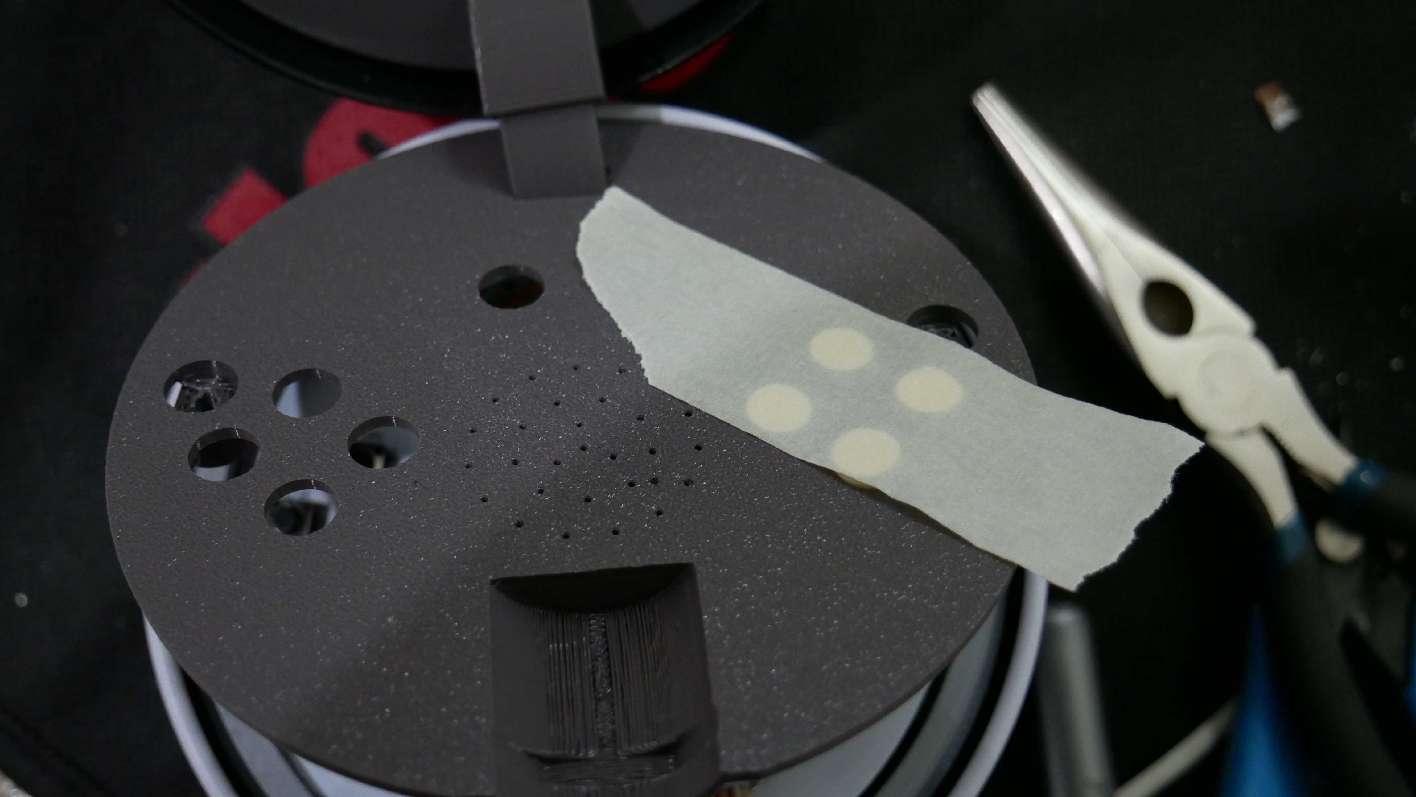
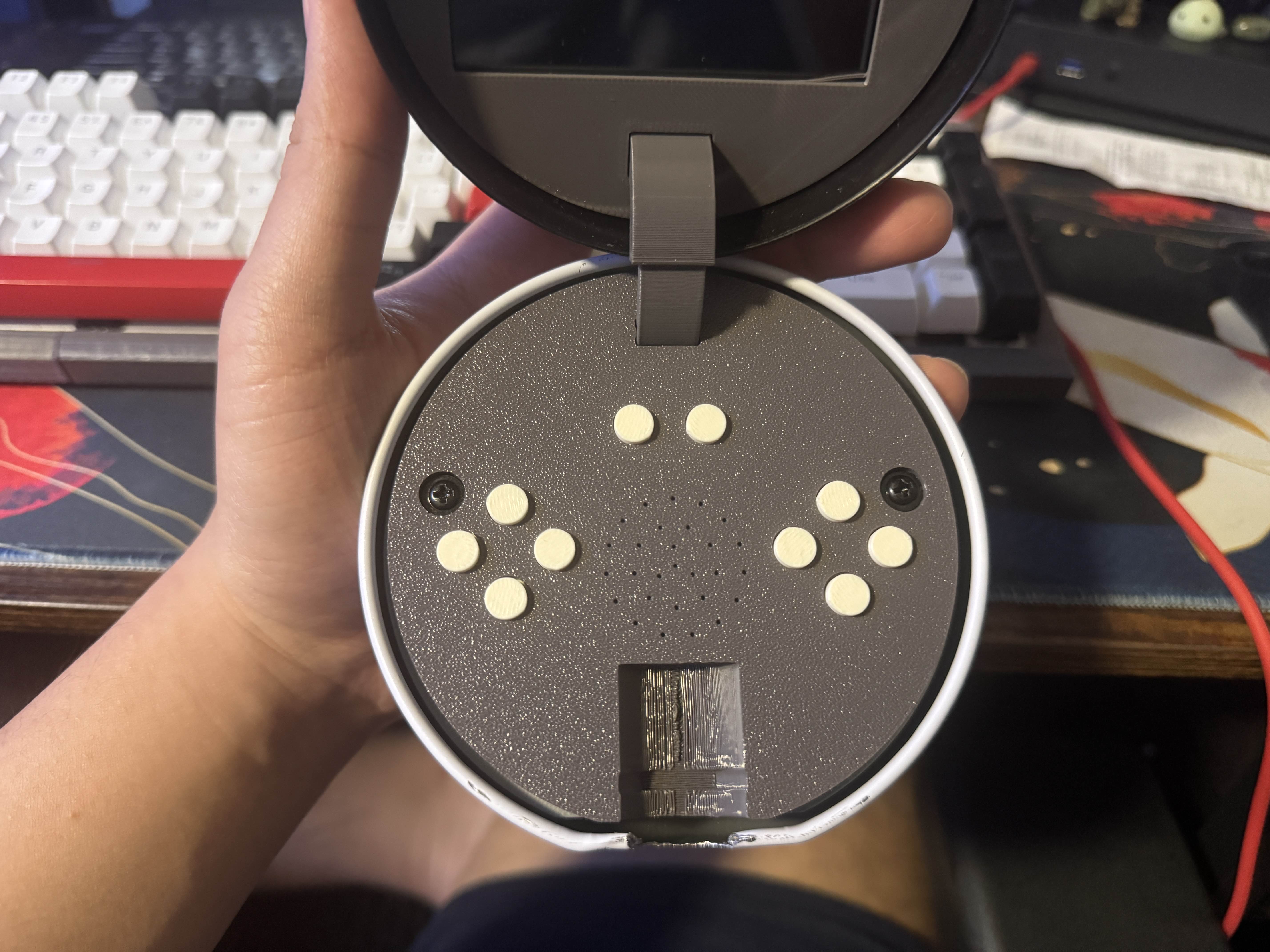
> Lastly draw a center line on the back of the faux button and use the epoxy/hot-glue to glue the spacers on along the center line. In the video, I glued it to the ring as well, but the epoxy didn't hold, plus it doesn't really move when you put everything together so that part isn't really necessary.
Power Button
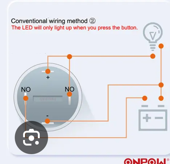
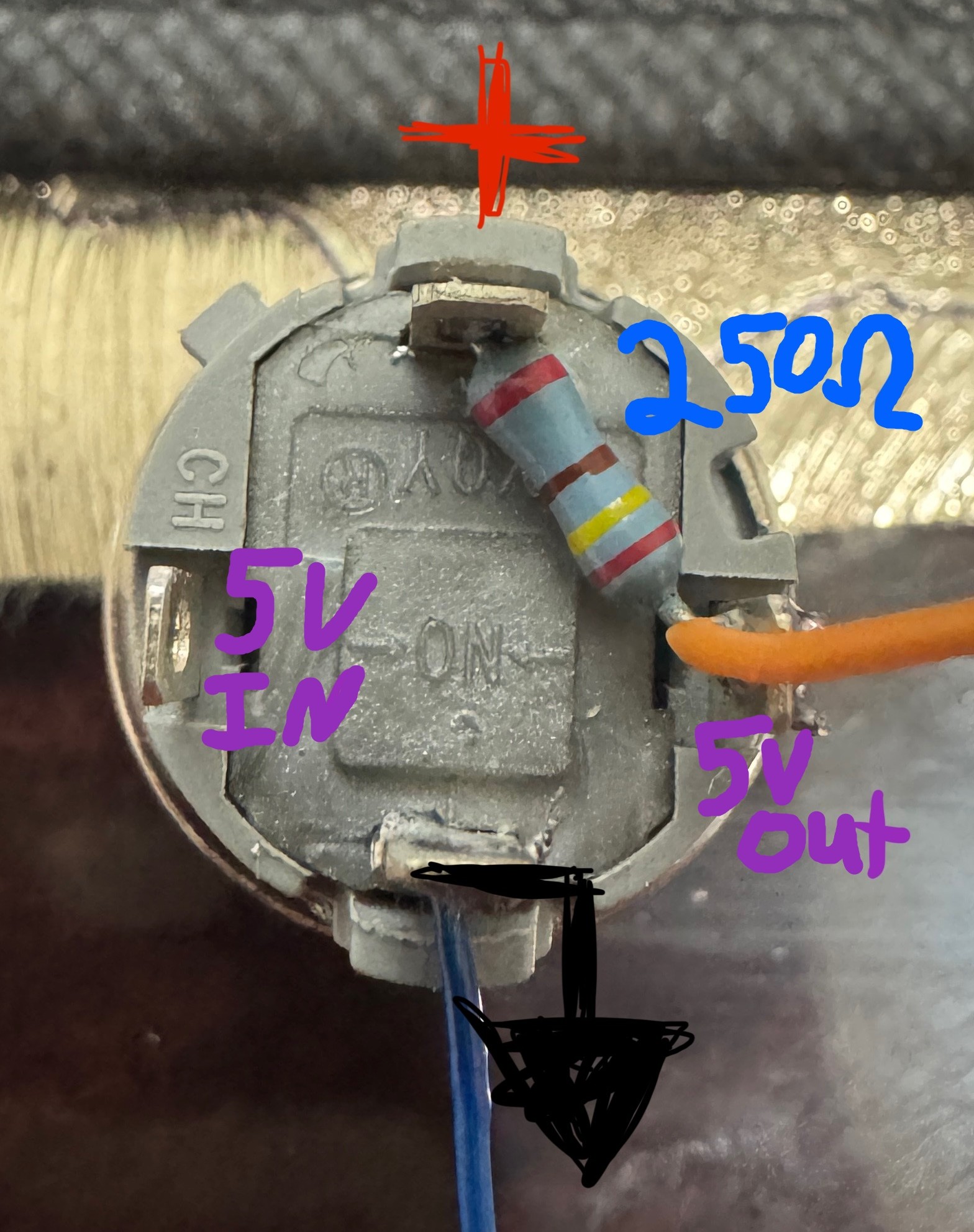
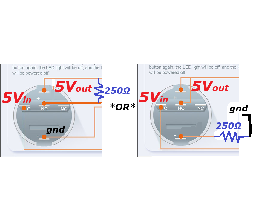
> The power button is simple whether you get a 4 leg or 5 leg button. Two of the legs allow you to pass a connection when the button is pushed. The other two are the positive and negative of the LED inside the button. I recommend using some low valued resistor (about 250-500 Ohms) between the output of the button and the positive of the LED to restrict current draw.
> You can use any wire that is thick enough to handle power to solder to the output and ground on the button, then put on the faux button and screw it onto the ring, keep the top half of the pokéball off
> If you are using a 5 legged button, it might be too long to fit without trimming the legs. In this case it might be hard to fit the resistor. It should be fine to wire "+" and "NO" together without the resistor, but to ensure limited current, I recommend extending the "NO" wire and attach the resistor between that and 5Vout. You can also just short "NO" and "+" and add the resistor to the "-" line then to gnd on the raspberry Pi. If needed, apply heat shrink to resistor to prevent shorts.

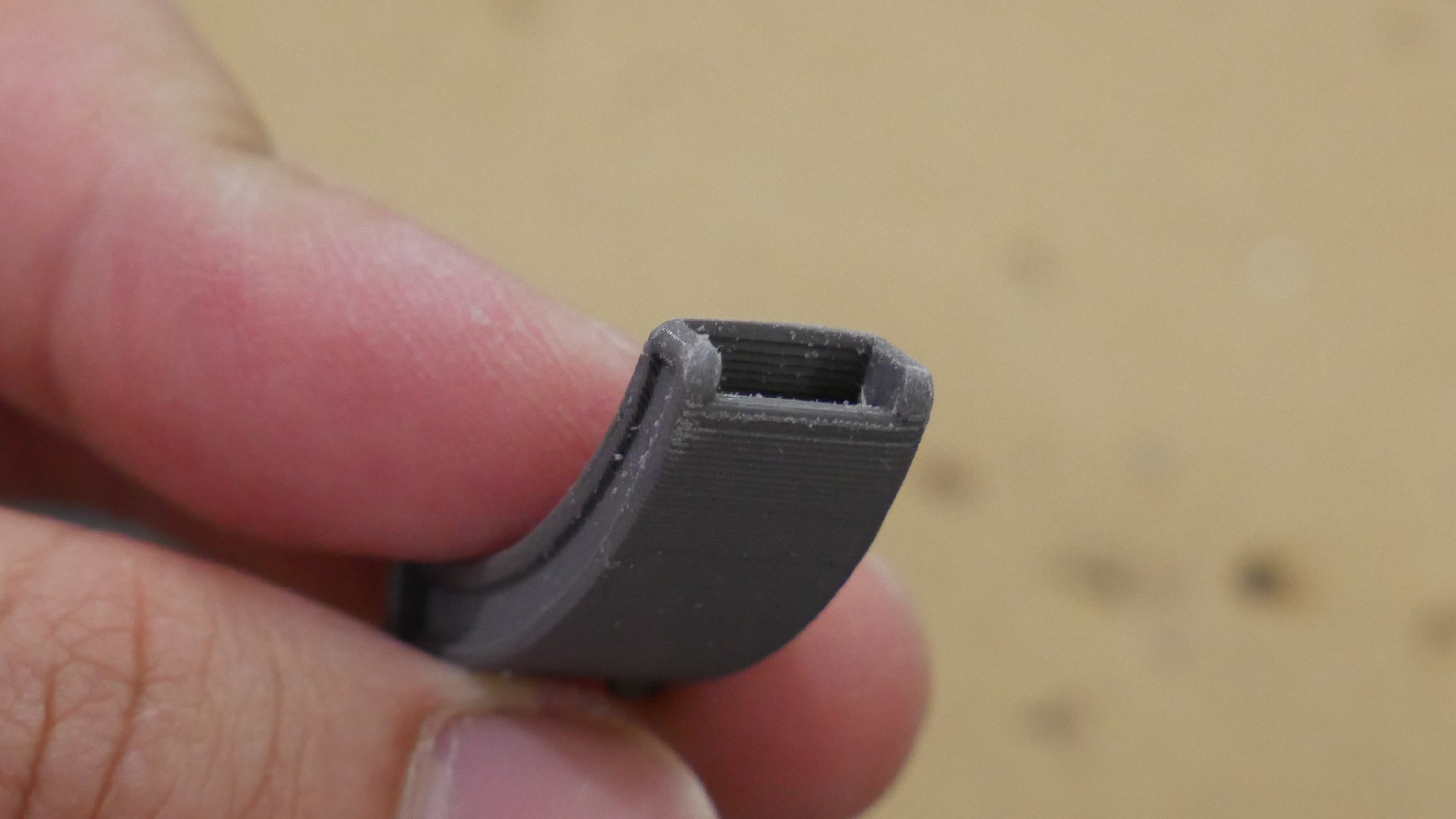
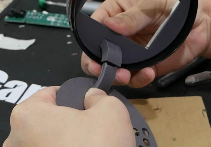
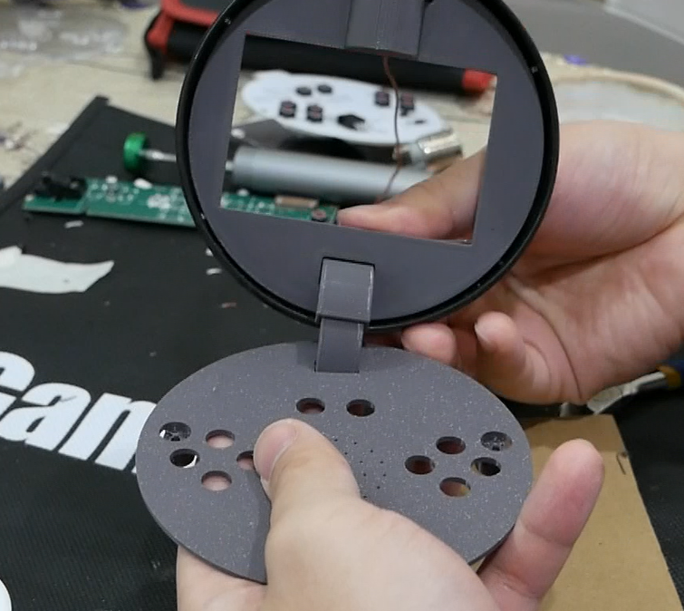
Hinge
> Insert the bottom hinge through the face plate, and the upper hinge through the top insert, then press the hinge together. *TIP* sand the top lip of the bottom hinge so that it is round and slides inside the upper hinge better. Slide them together to help break it in, make sure the motion is smooth, otherwise it needs more sanding or to be reprinted. *Note* if you make a transparent piece like I did, increase the tolerance a bit more, the UV printed parts expanded more than the FDM parts. Either that or sand down the contacting walls well and replace the bottom hinge because that catches in the upper hinge too much.
Wires
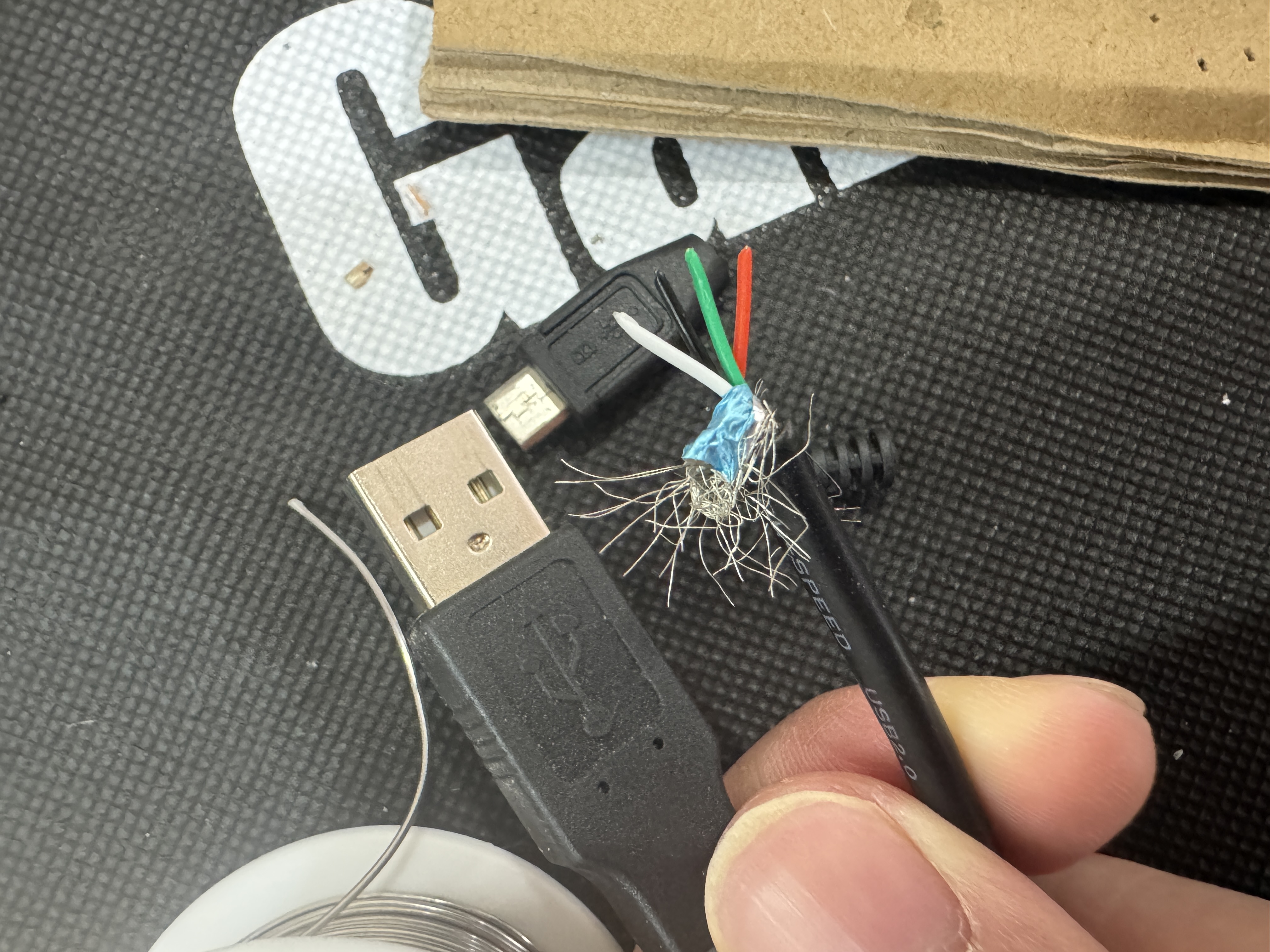
> I found that phone chargers have the ideal thickness and flexibility for this project, so I would recommend stripping some down especially if you can get one with data lines. I ended up using a whole meter or so since we need 14 wires. Each wire should be about 8-9in, more is better here since all excess can be hidden in the ball; we want enough to open the ball fully. Remember to reference the "Pinout" section and photo.
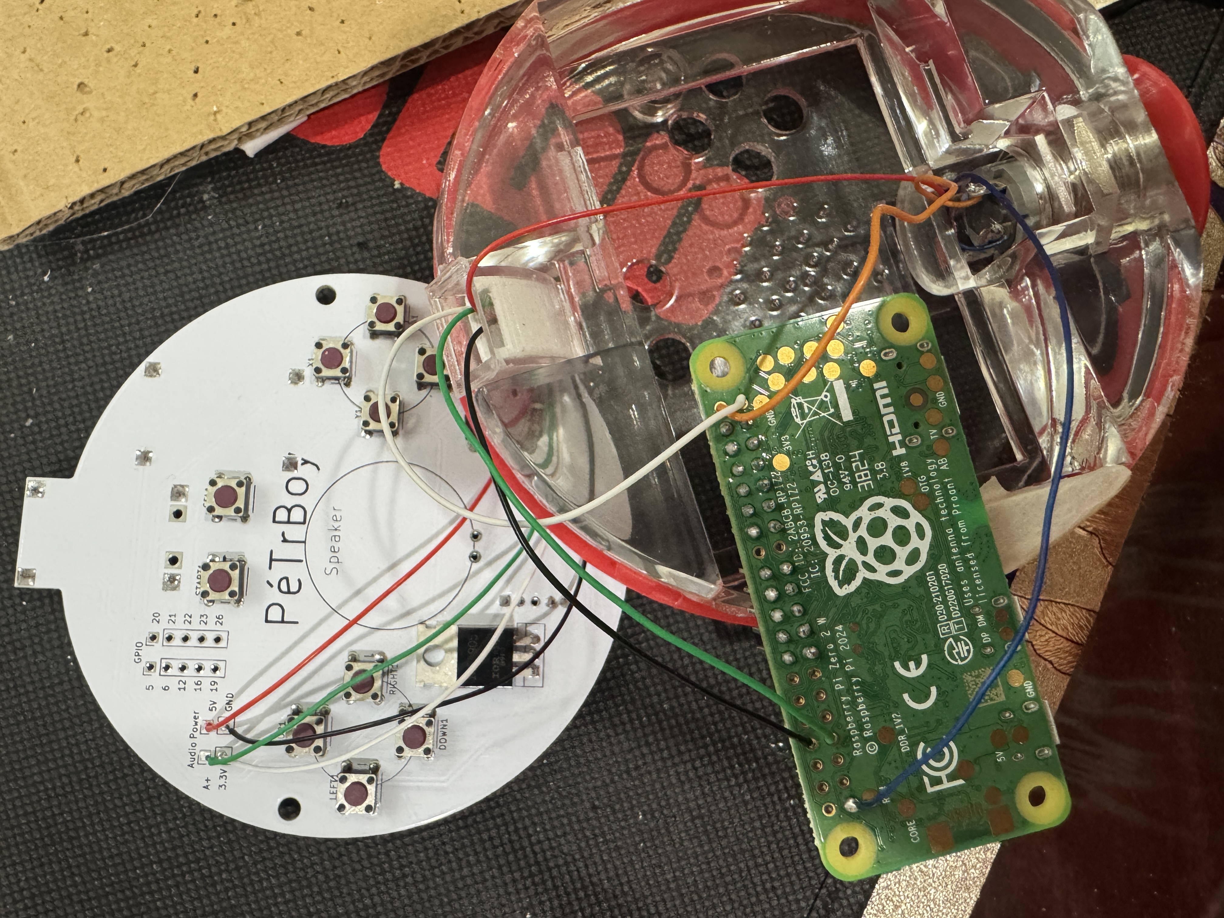
> First, we will wire up the 5V line and GND from the PCB. After soldering and labeling the wires to the PCB, feed them through the bottom hinge to the top. Solder Both of the GND from the PCB and button to the RaspPi. The 5V will go to the input of the button and the output wire of the button will go to the 5V pin on the Pi.
> Next, run two more wires for the 3.3V and audio input. The audio input should be GPIO 13.
> Then put on a movie and wire each button pin to their respective GPIO on the RaspPi. Remember, if you mess up, no worries, just reconfigure it in the retrogame config file or retropie settings.
> I would then plug the display in and the USB-C port to turn it all on and test the buttons before final assembly. *Note*, not all USB-C blocks will work with the charging module, if no LED's come on, try a different charging block.
Battery
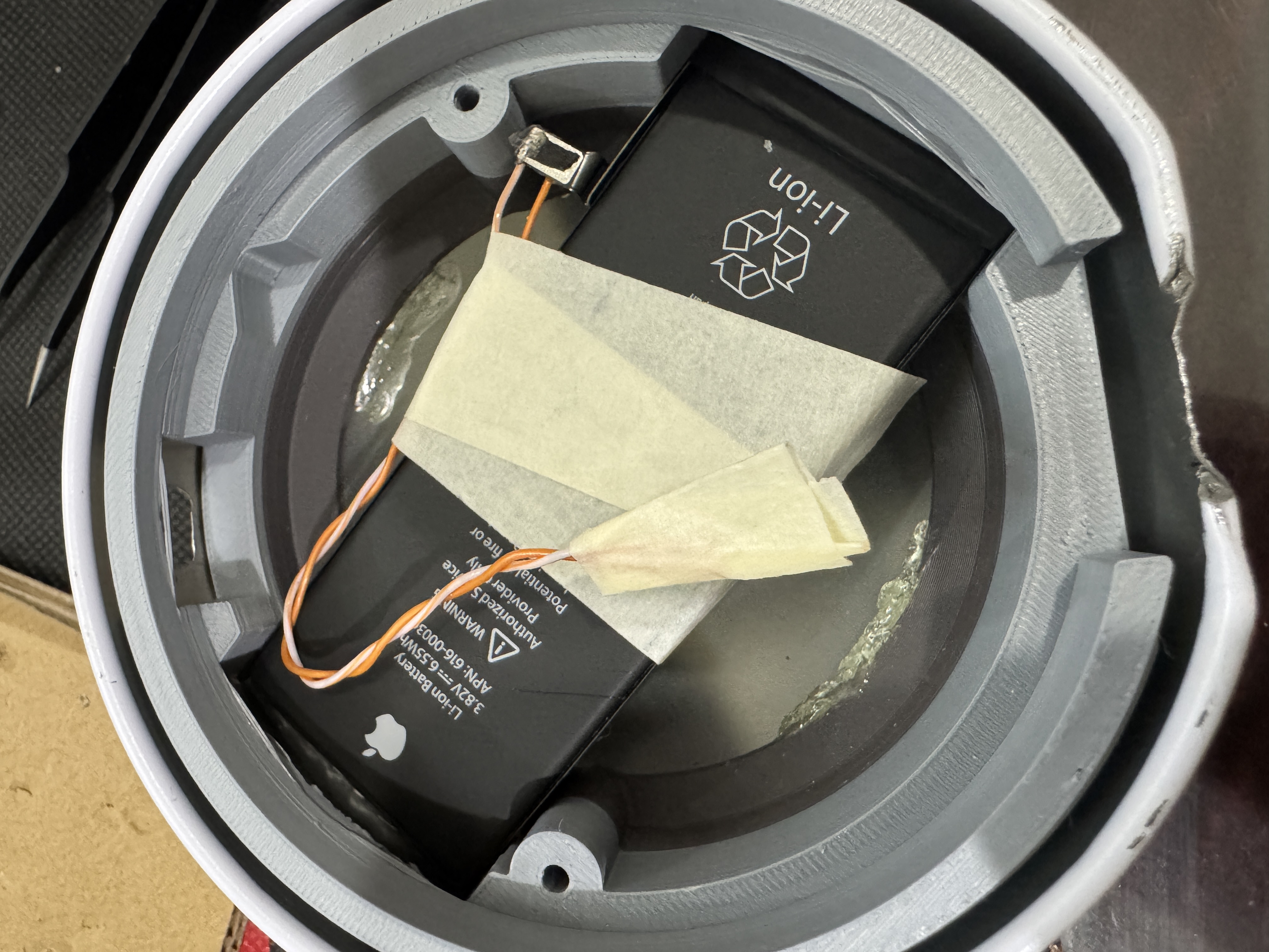
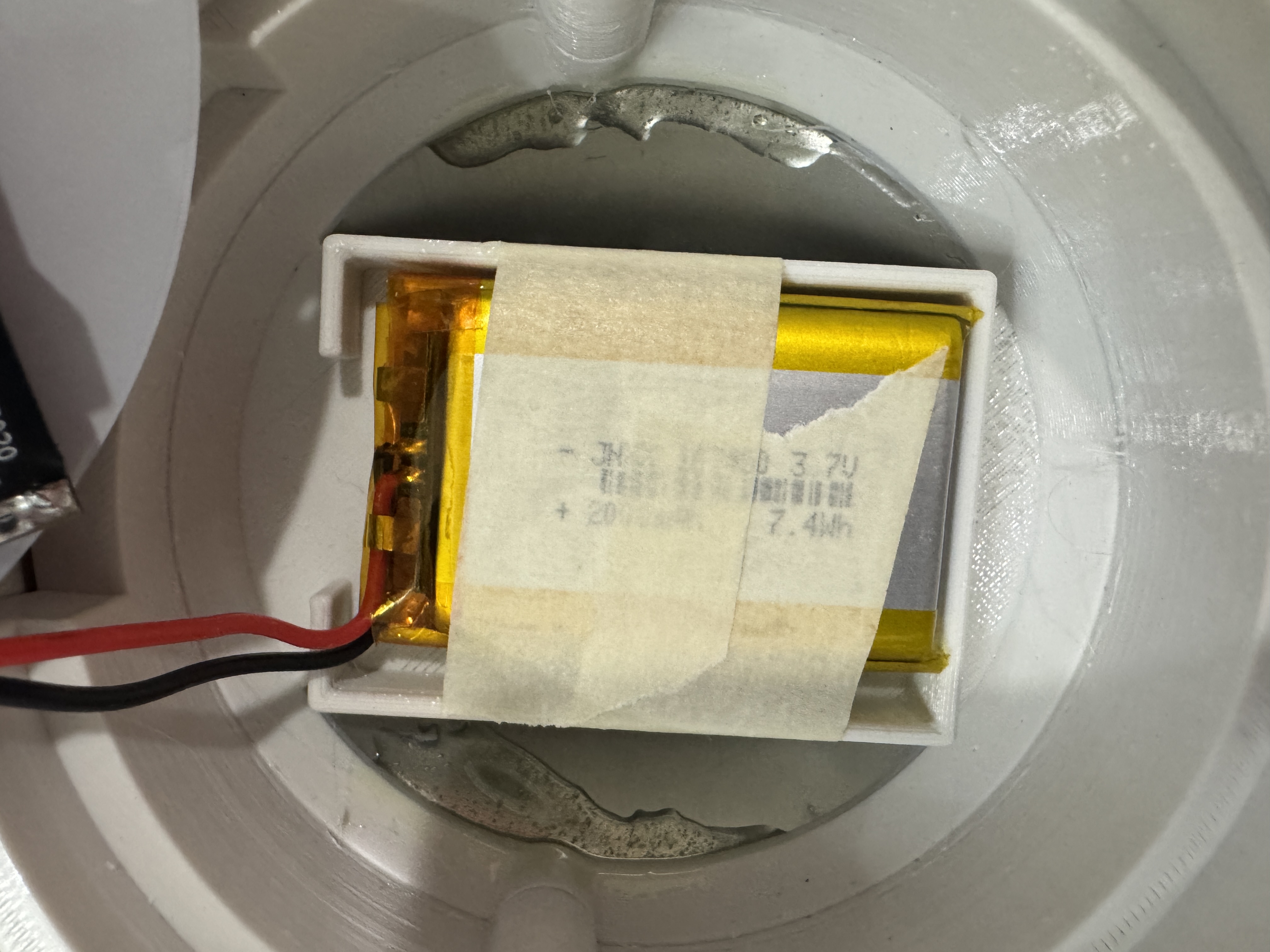
> The last thing to install is the battery, I first secured it to the bottom insert with tape (you should prob use electrical tape).
> The battery I have in the BOM has a header, you can pull the wires out or cut it off. *WARNING* When you do this, do it one wire at a time and be careful not to short the two together.
> Solder the battery's GND to the (-) of the USB-C charging module. Then tape it off to ensure of no accidental shorts. Solder the positive battery lead to the (+) of the module.
> Test to make sure that the battery charges and can power everything alone.
Final Assembly
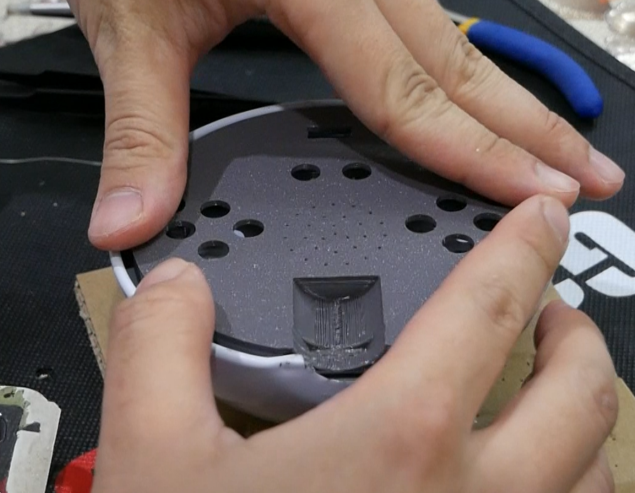
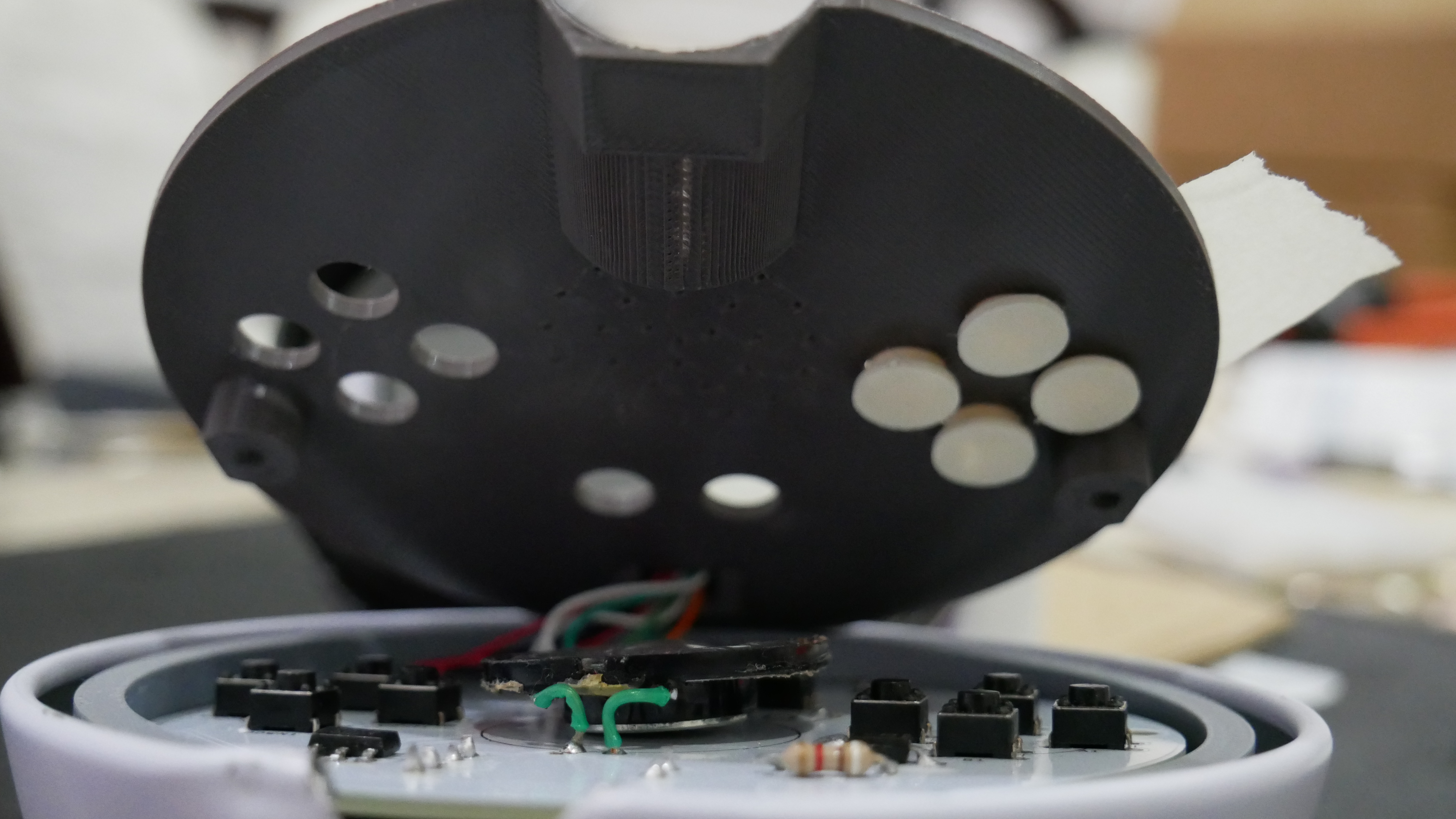
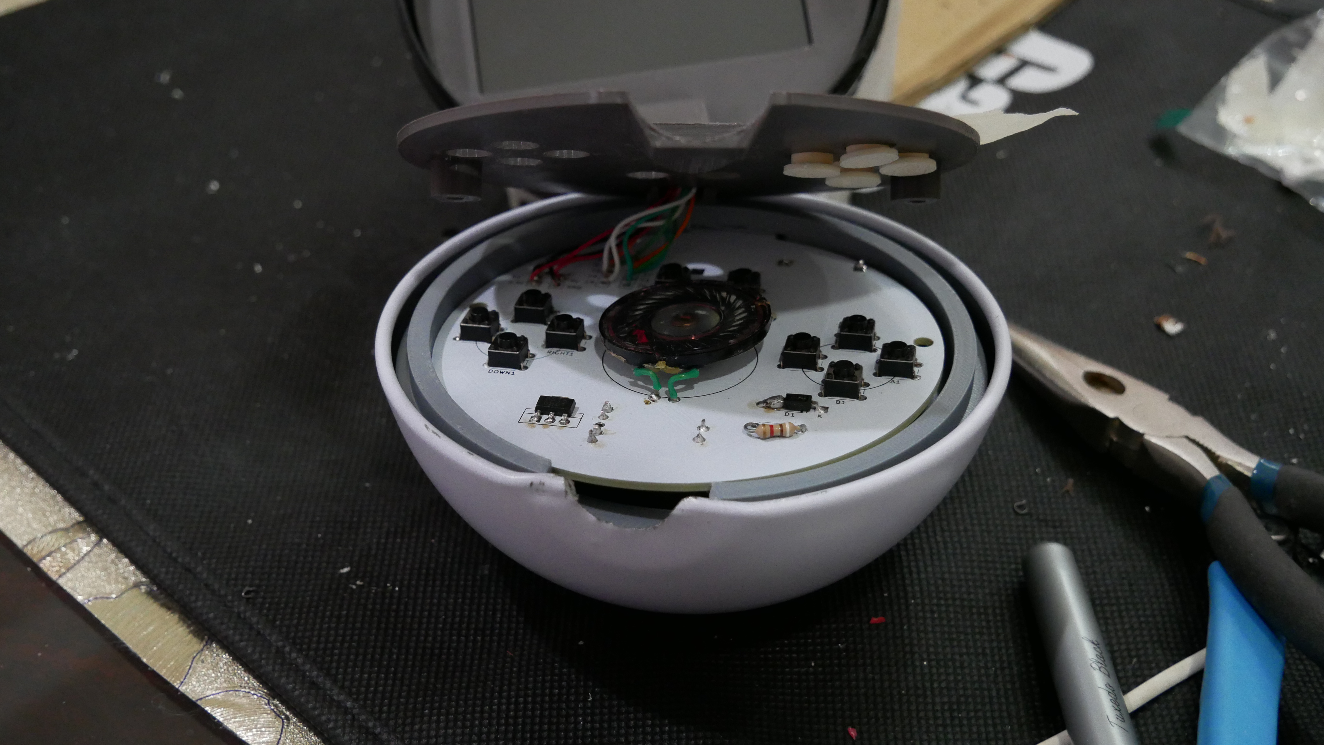
> Rest the PCB into the bottom insert. Manuver the wires up the hinge so that there is no resistance in trying to put the face plate on, there should be no wire blocking the buttons either. Apply tape to the top of the face plate where the button holes are, that way they stay in place during assembly.
> When everything sits nicely, screw the face plate down with M3 screws (more specifically M3*16*8mm)
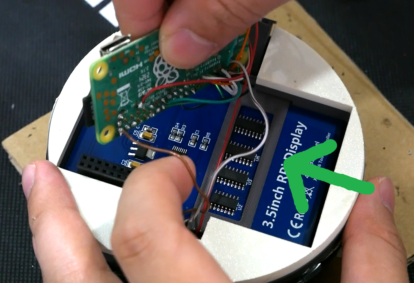
> It might be easier to slide the screen in place unattached from the Pi. When the screen is down, insert the lock bar to hold it in place, then reinstall the Pi. Hide all the wiring underneath the top half of the ball.
> Congratulations! You completed a PokéBoy!! Maybe... idk you didn't send me any pictures...
Closing Notes
> There were a lot of typos in making these instructions, I would like to thank Atara Collis and Jeff Racey for spotting my oopsies
> *FOR SAVE FILES* If you plan to play a game with a save file like pokemon, you need to save, then exit the game (press start and select at the same time) to save the file, it will not save if the ball powers down before exiting.
> I doubt anyone would read this far, but if you did, THANK YOU! This was an exciting opportunity given to be by PCBWAY, and I couldn't have asked for a better first project with them.
> There are plenty of things wrong with this project though, such as a better adhesive than epoxy would be nice. I think using silicon between the ring and the top insert might be a good idea but it could be messy and am unsure how that would hold up.
> I think if you overclock the system it would yield better performance, but that might cause too much strain on the battery and a heatsink would be required... but the system is enclosed in a tin ball so I am unsure how effect that heat dissipation would be either way.
> I definitely would source a better battery, 2000mAh might not last long enough for the best gameplay (about 2-3hrs) and the ball can definitely fit a bigger battery. Just make sure the voltages are compatible with the charging module.
> There is also no real power indicator since I did not really have enough time to design that, but it's probablt possible. If you did the "Display ADVANCE" step, the screen does start glitching out when the power gets low, so I suppose that can be used as a bad power indicator haha.
> Other than that, this was a really fun project to do, and in a way, you can finally catch your own Pokémon in a Pokéball! haha
Additional Resources That Helped Me
> This video by Bytes N Bits is a good overview in how to install and use retropie
> There is a much better build guide for a retropie handheld than I could ever make, check out this video then check out their website, it is so well detailed.
> This one helped me in designing the power circuit for the unit